If you’re setting up a weather station and don’t want a mess of cables, daisy chaining your sensors is a smart solution. It’s clean, simple, and perfect for connecting many digital weather sensors.
What Is a Daisy Chain?
A daisy chain is a method of connecting devices one after the other using a single data line. Imagine a line of people holding hands. The signal passes from one device to the next, just as a message would pass from one person to the next.
In weather stations, this means that each sensor is connected in a row and they all share the same communication cable. This method is particularly effective with digital sensors that use RS-485 and Modbus RTU.
How Does a Daisy Chain Work?
Let’s go step by step using SEVEN Sensor’s devices with RS-485 Modbus RTU, which is one of the most reliable communication systems for weather sensors.
- Use Digital Sensors Only
All sensors must use the Modbus RTU protocol. Each sensor has:
- A data input/output port
- A unique Modbus address (like a name, so it knows when it’s being called)
- Shared Data Line
All sensors use the same data wires. You connect them in series as you see in the figure below:
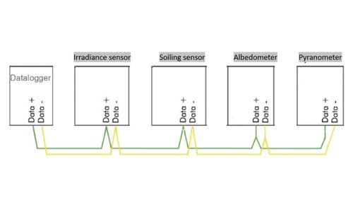
Each sensor knows when to “speak” and waits for the datalogger to ask.
- Parallel Power Supply
The communication line is shared, but power is delivered in parallel. That means all sensors are powered from the same source, like multiple appliances plugged into the same power strip.
- Polling with Addresses
The datalogger in this topology is the master, and acts like a teacher taking attendance in an organized order:
- “Sensor 1, what’s the temperature?”
- “Sensor 2, what’s the Irradiance?”
Only the sensor with the matching address replies. No mix-ups.
- Termination Resistors
To keep data flowing smoothly, resistors are placed at both ends of the RS-485 cable. They stop signal problems like echo or reflection.
Why Use Daisy Chain for Weather Sensors?
Using a daisy chain has many benefits:
| Benefit | What It Means |
| Fewer cables | One data cable connects all sensors |
| Simple installation | Easy for long distances (up to 1.2 km) |
| Easy to expand | Just add more sensors in line |
| Neat and clean | Less mess, easier to maintain |
Topologies to Avoid in RS-485 Sensor Networks
While daisy chaining is the recommended method for connecting digital sensors, some wiring topologies should never be used in RS-485 systems. Star networks, ring setups, and backbones with clusters or long stubs can lead to serious communication problems like signal reflection, data loss, or complete failure. These configurations might seem organized at first glance, but they break the basic rules of RS-485 communication.
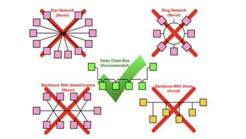
This diagram shows that the daisy chain bus is the only recommended RS-485 wiring method for reliable sensor communication
Can I Daisy Chain Analog Sensors?
No. Analog sensors cannot be daisy chained. Here’s why:
- Analog sensors output raw voltage or current signals and do not have an address or built-in communication protocol. This means each sensor must be connected directly to a dedicated input channel on the datalogger.
- If multiple analog signals share one cable, they interfere with each other, and it this case the datalogger cannot tell which sensor the signal is coming from.
But digital sensors have addresses and only respond when asked.
Other Sensor Wiring Methods (Comparison)
While daisy chaining is great, here are some other connection types:
| Method | Best Use Case | How It Works |
| Star | Few sensors | Each sensor connects directly to logger |
| Multiplexer | Many analog sensors | Switches between sensor inputs |
| Wireless | Remote or isolated areas | Uses Wi-Fi or LoRa |
| Ethernet | Smart or IoT systems | Each sensor has an IP address |
Still, for most weather and solar setups, RS-485 daisy chain is the top choice. Trusted brands like SEVEN Sensor recommend it to keep wiring simple and avoid problems during setup or operation.
Real-World Example Using SEVEN Sensor
Let’s say you’re building a weather station. You use:
- 1 double oriented Irradiance Sensors (POA)
- 1 Humidity & Temperature Sensor
- 1 Pyranometer (GHI)
How You Connect:
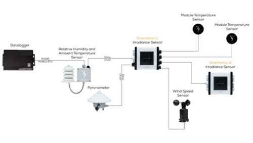
- Connect the data logger to the first sensor using RS-485.
- Then, connect the second sensor to the first.
- Keep connecting them one by one.
All sensors have unique Modbus addresses and share the same communication cable with 2 wires. One cable. One data logger. No cable chaos.
Daisy chaining your meteorological sensors is like building a smart team, where everyone knows their role and speaks when asked. It’s tidy, reliable, and ready for expansion.