In Solar Energy Systems (SPP), accurate and reliable data transmission of sensors is of great importance. However, a detail that is often overlooked is the cable length between the sensor and the control unit. Especially in sensitive measurement devices such as PT1000 temperature sensors and wind sensors, long cable distances can cause serious signal attenuation or communication errors.
In this article, we will evaluate the effects of cable length on the sensor signal according to the communication methods used, and share practical solutions that can be taken to prevent attenuation
How Does Cable Length Affect the Sensor Signal?
Electrically, the extended cable creates a resistance (R), capacitance (C) and inductance (L). This can lead to the following negative effects:
- Voltage drop: Analog output signals show deviations from the measured value.
- Interference effect: Electromagnetic interference in the environment can interfere with the sensor signal.
- Time delay and data loss: Transmission quality deteriorates in digital protocols.
Especially in long-distance field applications, the type of communication used directly determines the extent to which these effects are felt.
Cable Length in Analog Communication (4-20 mA vs 0-10V)
4-20 mA Signals
- As it is current-based, cable resistance has little effect on signal quality.
- Ideal for long distances. Up to 1000 meters of safe transmission can be provided.
0-10V Signals
- It is voltage based. Directly affected by cable resistance.
- Sensitivity loss may occur beyond 50-100 meters.
- Be sure to calculate the voltage drop as the cable distance increases in 0-10V signal.
Cable Length in Digital Communication (Modbus RTU)
Modbus RTU is an RS485-based protocol that is widely preferred in the field.
- It is resistant to long distance thanks to its differential signal structure.
- With a low baud rate of 9600 bps, communication over 1000 meters can be achieved.
- However, topology, termination resistance and cable quality play a big role.
As SevenSensor, we provide secure data transmission between the field and the central system by using Modbus RTU in all our RS485-based sensors. You can browse all our meteorological sensors here.
Signal Attenuation Prevention and Protection Methods
We recommend you to use the cables recommended by SEVEN. We strongly discourage the use of splices, exposed cable shields or improper grounding of the cables used in our sensors.
1. Appropriate Cable Selection
- Electromagnetic interference can be reduced by using shielded cables.
- Low resistance and high quality copper cables are preferable.
2. Use of Termination Resistor (Modbus RTU)
- Reflections can be avoided by adding 120 ohm resistors at the beginning and end of the network.
- Connections suitable for the topology should be used. For example, daisy chain connection should be preferred and star topology should be avoided. You can find our article on these topologies
3. Grounded Protection
- The shield of the cable must be connected to earth at a single point.
- Cables must never be spliced or the cable shield must not be left exposed.
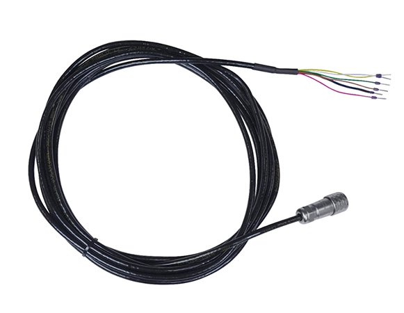
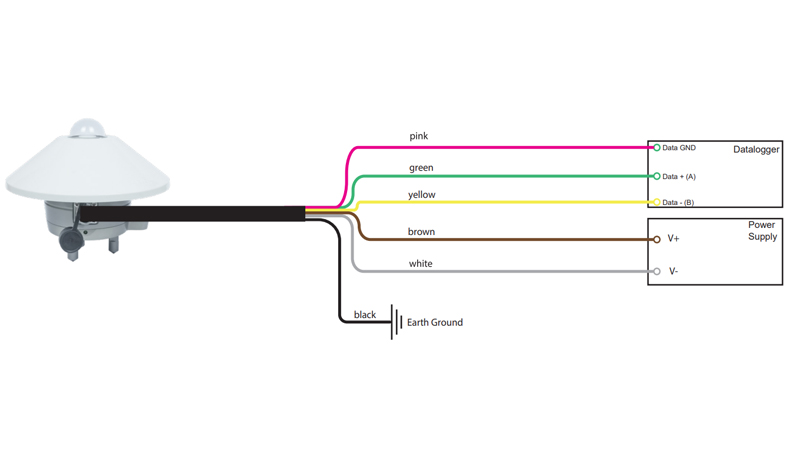
- SEVEN Sensors, like the 3S-TP-MB-A Thermopile Pyranometer shown below as an example, all our sensors must have a earth ground connection to the black cable connection. The 3S-TP-MB-A Thermopile Pyranometer was successfully tested with RS485 even on a 1200 meter cable. It worked with an error rate of 0.2% when grounding and resistance rules were applied.
Cable length, splicing cables, leaving the ground end of the cable open, not making the ground connection are parameters that are often ignored but can lead to serious consequences in field applications. Although different effects are seen according to analog and digital communication methods, these problems can be easily controlled with the right cable selection and protection measures.
As Seven Sensor, we offer meteorology sensors in analog and RS485/Modbus solutions with our engineers to provide the connection methods suitable for field conditions. You can contact us for more information.
Frequently Asked Questions (FAQ)
Which signal type should I choose if the cable is long?
Prefer 4-20 mA or Modbus RTU. It is safer not to exceed 50 meters in 0-10V systems.
Why do we install a resistor on the Modbus line?
Termination resistors are essential to prevent signal reflections on long cables.
What happens if I make a splice in the cable?
The impedance changes at the joints. This causes data loss or deviations in sensor readings.