

Irradiance Sensor With Modbus RTU Output – 3S-IS
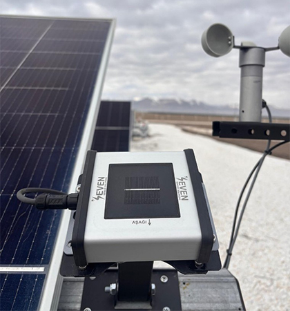
The 3S-IS Irradiance Sensor is designed for solar PV plants that require accurate irradiance and cell temperature measurement with Modbus RTU communication. Delivered with a mounting bracket and cable, this UV-protected, plug-and-run sensor integrates easily into existing PLC, SCADA, or datalogger systems via RS485.
TECHNICAL SPECIFICATIONS OF IRRADIANCE SENSOR
| Item Code | 3S-IS, 3S-IS-1, 3S-IS-2, 3S-IS-2T, 3S-IS-3, 3S-IS-4, 3S-IS-5 |
| Reference Cell | Monocrystalline Silicon (31 mm x 31 mm) |
| Current Shunt | High precision shunt resistor directly soldered to the terminals of the cell |
| Irradiance Range | 0 – 1600 W/m² |
| Uncertainty | ≤1%, as per IEC61724-1 standard Class A |
| Resolution | 0.1 W/m², as per IEC61724-1 standard Class A |
| Response Time | 1 sec. as per IEC61724-1 standard Class A |
| Drift | Very small drift of <0.3%/ year |
| Field of View | Larger than 160° as per IEC61724-1 standard Class A |
| Tilt-Azimuthal Angle | 0°- 0° , ≤ 1°; as per IEC61724-1 standard Class A |
| Output Rate | 1/s |
| Data Output | RS485 up to 38400 Baud |
| Communication Protocol | Modbus RTU |
| Power Supply | 12 to 30 V DC |
| Power Consumption | 30 mA max @24 VDC |
| Electrical Connection | 3 m LIYYC11Y PUR Cable, UV and Weather Resistant |
| Galvanic Isolation | 1000 V between power supply and RS485 bus |
| Cell Temperature Sensor Type | PT1000 Class A as per EN 60751 |
| Operating Temperature Range | -40°C to +85°C |
| Operating Humidity Range | 0 to 100 % |
| Box Dimensions | 140 mm x 110 mm x 42 mm (W x L x H) |
| Weight | 0.3 kg |
| IP Rating | IP54 (IP65, IP68 options) |
| Sensor Housing Material | Aluminum |
| Compliant Standard | IEC 61724-1:2021 and IEC 60904 |
| Calibration | Each sensor is calibrated under Class AAA Sun Simulator as per IEC 60904-2 and IEC 60904-4 by using a reference cell calibrated by ISFH-Germany |
| Test | The test is carried under natural sunlight by using a calibrated reference cell from Fraunhofer ISE, Germany |
What Does an Irradiance Sensor Do?
Solar irradiance is the amount of solar power received per unit area (W/m²). Monitoring irradiance is essential for evaluating the performance of PV plants. The 3S-IS sensor measures irradiance using a monocrystalline silicon solar cell, while also compensating for temperature effects thanks to its built-in PT1000 cell temperature sensor.
How Does the 3S-IS Sensor Work?
- A monocrystalline solar cell absorbs sunlight and generates current.
- A precision shunt resistor converts this current into measurable signals.
- The temperature sensor at the back of the cell corrects deviations caused by heat.
- An electronic card processes these signals and calculates compensated irradiance values in W/m².
- Data is sent to receiver units via RS485 using Modbus RTU.
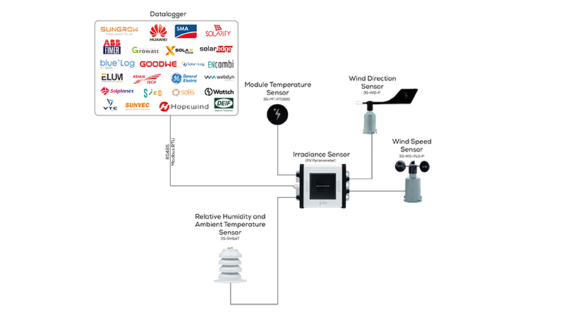
Because of its flexible design, the 3S-IS can also link with additional environmental sensors, turning it into a complete monitoring hub for PV plants.
Why Choose the 3S-IS Irradiance Sensor?
- Trusted accuracy: IEC 61724-1 Class A compliance with uncertainty ≤1%, calibrated as per IEC 60904-2 standards.
- Fast results: Response time of one second for real-time decision making. It can be reduced to 500 milliseconds upon request.
- Built to last: A UV-protected IP54 aluminum housing with optional IP65/IP68 ensures reliable operation in demanding outdoor environments.
- Quick setup: Plug-and-run design means fewer installation errors and faster commissioning. Supplied with mounting bracket and cable. Easy integration with any Modbus-compatible PLC, SCADA, or datalogger.
- Expandable: Supports connection of multiple external sensors (temperature, wind, humidity) for more complete monitoring.
Available Models of the 3S-IS Irradiance Sensor
All models below are IEC 61724-1:2021 Class A compliant, factory-calibrated, and built with the same durable construction. The only difference is the number and type of external sensors that can be connected via RS485 Modbus RTU.
| Model | Communication | Uncertainty | External Sensor Options |
| 3S-IS | RS485 Modbus RTU | ≤1%, as per IEC61724-1 standard Class A | No external sensor can be connected |
| 3S-IS-1 | RS485 Modbus RTU | ≤1%, as per IEC61724-1 standard Class A | Ambient Temperature Sensor OR Module Temperature Sensor |
| 3S-IS-2 | RS485 Modbus RTU | ≤1%, as per IEC61724-1 standard Class A |
Ambient Temperature Sensor OR Module Temperature Sensor
Wind Speed Sensor
|
| 3S-IS-2T | RS485 Modbus RTU | ≤1%, as per IEC61724-1 standard Class A |
Ambient Temperature Sensor
Module Temperature Sensor
|
| 3S-IS-3 | RS485 Modbus RTU | ≤1%, as per IEC61724-1 standard Class A |
Ambient Temperature Sensor
Module Temperature Sensor
Wind Speed Sensor
|
| 3S-IS-4 | RS485 Modbus RTU | ≤1%, as per IEC61724-1 standard Class A |
Ambient Temperature Sensor
Module Temperature Sensor
Wind Speed Sensor
Wind Direction Sensor OR Relative Humidity Sensor
|
| 3S-IS-5 | RS485 Modbus RTU | ≤1%, as per IEC61724-1 standard Class A |
Module Temperature Sensor
Wind Speed Sensor
Wind Direction Sensor
Relative Humidity and Ambient Temperature Sensor
|
Frequently Asked Questions (FAQ)
Which datalogger brands are SEVEN irradiance sensors compatible with?
SEVEN irradiance sensors are compatible with a wide range of well-known datalogger brands, including:
ABB
Bluelog
DEIF
Elum
Encombi
Fimer
General Electric
GoodWe
Growatt
Hopewind
Huawei
Kehua Tech
Sico
SMA
Solplanet
SolarEdge
Solar-Log
SolaX Power
Solis
Sungrow
SUNVEC
Wattch MET
Webdyn
What is the uncertainty of the irradiance sensor?
The uncertainty is ≤1%, fully compliant with IEC 61724-1 Class A requirements.
Can this sensor connect directly to my SCADA system?
Yes, as long as your system supports RS485/Modbus RTU, the sensor will be fully compatible.
How are the sensors tested and calibrated?
Each irradiance sensor is calibrated under a Class AAA Sun Simulator as per IEC 60904-2 and IEC 60904-4, using a reference cell calibrated by ISFH-Germany.
The sensors are tested in natural sunlight against a reference cell calibrated by the Fraunhofer ISE Institute.
How often should I recalibrate the sensor?
Recalibration every 2 years is recommended by IEC standards for maximum accuracy.
Where can I recalibrate the irradiance sensor?
SEVEN Sensor provides calibration services at its facilities. Calibration is performed using a Class AAA Sun Simulator, in accordance with IEC 60904-2 and IEC 60904-4 standards, and referenced against a calibration cell certified by the ISFH Institute in Germany.
Additionally we offer user-friendly interface where users can recalibrate the sensors in their home country and enter the new calibration values into the system.
Are the irradiance sensors Class A?
Yes. All SEVEN irradiance sensor models — 3S-IS, 3S-IS-1, 3S-IS-2, 3S-IS-2T, 3S-IS-3, 3S-IS-4, and 3S-IS-5 — are Class A as per IEC standards, with the exception of the low-cost irradiance sensor.
What is the price of irradiance sensors?
Depending on the model and included accessories, the 3S-IS series is available between 200 and 530 EUR.
Does the sensor include a cable?
Each unit comes with a 3 m LIYYC11Y PUR cable (UV and weather resistant) with 6 wires twisted (including ground for both Data & Power). Other lengths are available on request.
What makes this sensor different from analog models?
Unlike analog outputs, Modbus RTU provides digital communication, minimizing signal loss over long distances and allowing multi-sensor connections.
What are the delivery times?
Small orders: approx. 3-5 days
Bulk orders (100 pcs): approx. 4-6 weeks
How do I set up the sensor?
Follow our user manual, setting instructions and YouTube video guides, which include step-by-step instructions for configuring the sensors with well-known datalogger brands such as SMA, Huawei, and Sungrow. We also provide remote setup support if needed.
What is the warranty?
All 3S-IS sensors come with a 5-year warranty.
What external sensors can be connected to the irradiance sensor?
The SEVEN irradiance sensor can also function as a hub, supporting the connection of external sensors such as:
Module temperature sensors
Ambient temperature sensors
Wind speed sensors
Wind direction sensors
Relative humidity sensors