The most important and direct effects on the performance of the PV plant are irradiance in plane of PV array, PV cell temperature, and shading losses due to soiling or snow. The effect of PV cell temperature on the performance of the PV plant can be explained as follows:
Photovoltaic modules start to generate electricity when they receive sunlight. While some of the radiation coming from the sun is converted into electrical energy, some of it emerges as heat energy. This event causes the PV cells to heat up. With the heating of the PV cells, the short circuit current (I) of the PV modules increases, while the open circuit voltage (V) decreases, thus reducing the electrical efficiency.
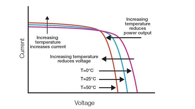
Figure 1 – Temperature effect on I-V curves
In order to determine the effect of PV module temperature on the performance of the PV plant, PV module temperature is measured with temperature sensors attached to the back of one or more modules. As specified in the “IEC 61724 Photovoltaic system performance – Part 1: Monitoring” standard, the number of sensors to be used according to the system size is given in Table 1. Again according to IEC 61724-1, the measurement uncertainty of temperature sensors, including signal conditioning, must be ≤ 2 °C.
| PV Plant size (AC) | Number of sensors |
|---|---|
| < 5 MW | 6 |
| ≥ 5 MW to < 40 MW | 12 |
| ≥ 40 MW to < 100 MW | 18 |
| ≥ 100 MW to < 200 MW | 24 |
| ≥ 200 MW to < 300 MW | 30 |
| ≥ 300 MW to < 500 MW | 36 |
| ≥ 500 MW to < 750 MW | 42 |
| ≥ 750 MW | 48 |
Table 1 – Relation between system size (AC) and number of sensors for PV module temperature
Module temperature varies across each module and across the array and substantial differences in temperature may be observed. For example, strong winds blowing parallel to the module surfaces may introduce a temperature difference > 5 °C. Similarly, a module may be cooler near a frame that is clamped to the rack, since the rack may act as a heat sink. Concentrator modules may show even larger variations between the outer edges of the heat sink and the heat sink that is closest to the concentrated light.
Therefore, care shall be taken to place temperature sensors in representative locations such that the desired information is obtained. For performance monitoring, a number of temperature sensors should be distributed throughout the system so that the average temperature can be determined.
In addition, when the array consists of more than one module type or includes sections with different orientations or other attributes that can affect temperature, at least one temperature sensor is required for each module type or section type, and additional sensors, if required according to array size, are to be distributed in a representative manner amongst the different module types and section types.
Module temperature sensor and material selection
The sensor type and attachment method can have significant impacts on the measured temperature, leading to significant measurement errors. These errors are affected primarily by the contact between the sensor and the module’s rear surface, the amount and type of insulation placed over the sensor, and the amount and type of adhesive used.
Optimum sensor types and optimal tapes are explained in IEC 61724-1 as follows:
Preference should be given to flat probes designed specifically for long-term surface measurements. Thin-film thermocouples of types T or E are generally acceptable. Small form- factor RTD and thermistor elements may be utilized provided air gaps are minimized when applying the tape overlay. However, bead thermocouples, unpackaged resistive elements, and devices encased in cylindrical probe heads should be avoided when possible.
Figure 2 – PV module temperature sensor and tape
To minimize errors and to weather-proof the temperature sensor, reinforcement of the sensor and sensor leads is recommended. This may be accomplished by applying an adhesive overlay or tape.
Adhesive overlays and tapes should be fabricated from materials resistant to the effects of temperature, humidity, and ultraviolet radiation. Avoid tapes not intended for use in securing sensors to surfaces – such as electrical tape, duct tape, aluminized cloth tape, foil tape, or packaging tape – as they may be structurally weak and because their adhesives tend to dry out over time or flow at elevated temperatures. Polyimide tapes (such as Kapton) are known to be susceptible to embrittlement when exposed to ultraviolet radiation and moisture in the presence of oxygen (air) and should be avoided for long-term installations. Polyester is probably the most appropriate overlay material since many backsheets are constructed of multi-layer polyester and this material holds up well against moisture, temperature, and ultraviolet light. Pressure-sensitive silicone adhesive is generally applied to polyester tapes and is recommended.
When using an overlay or tape, minimize air gaps as much as possible. Pockets of trapped air will temper the sensor response, thus negatively impacting the performance of the measurement system.
Sensor attachment
How to attach a temperature sensor to the PV module is clearly stated in the “IEC 61724 Photovoltaic system performance – Part 1: Monitoring” standard. According to this standard, temperature sensors can be attached to the PV module in two different ways, permanent or temporarily, depending on the area of use of the temperature measurement results. Again in IEC 61724-1, locations where temperature sensors can be attached in the PV module are described.
Sensor attachment location
Select a sensor location at the centre of a cell close to the centre of the module, avoiding boundaries between cells.
For crystalline silicon modules, select the centre of the centre-most cell within the module, or, when the module is built with even numbers of rows or columns of cells, select one of the cells closest to the centre.
For thin-film modules, place the sensor within the boundary of a cell near the centre of the module, avoiding scribe lines between adjacent cells if possible.
Figure 3 – Sensor attachment location on PV module
Permanent and temporary sensor attachment method
Permanent attachment is recommended when long-term monitoring is desired and the sensor will not be removed or relocated. For instance, when including back-of-module temperature measurements within a fielded data acquisition system.
Temporary attachment is recommended when the measurement sensor will need to be relocated or removed owing to the short-term nature of the monitoring, such as during commissioning or periodic maintenance.
Below are the steps of permanent and temporary attachment methods of a temperature sensor according to the IEC 61724-1 standard in detail.
- Clean the module’s rear surface and sensor element of oil and dust by using lint-free wipes dampened with a 70 % solution of isopropyl alcohol in distilled water. Allow all cleaned surfaces to dry completely before proceeding.
- Attach the sensor using the appropriate method:
- Permanent (see Figure 4):
- The adhesive should be confirmed to be compatible with the backsheet material so as to not affect the long-term integrity of the module.
- Mix a thermally conductive epoxy as per manufacturer instructions.
- Apply the adhesive to the side of the sensor element intended to contact the module surface. Do not over-apply the adhesive; it should be as thin as possible yet fully coat the surface of the sensor element.
- Place the sensor element in the selected location. Manipulate the sensor to remove air bubbles and obtain a uniform adhesive thickness.
- Apply a polyester tape overlay to maintain the sensor position while the adhesive cures and to provide long-term protection of the sensor element. Round die-cut shapes are ideal as their lack of corners reduces the potential of delamination. If round shapes are not available, significantly round the corners of the tape using scissors.
Allow the adhesive to cure as per the manufacturer’s instructions.
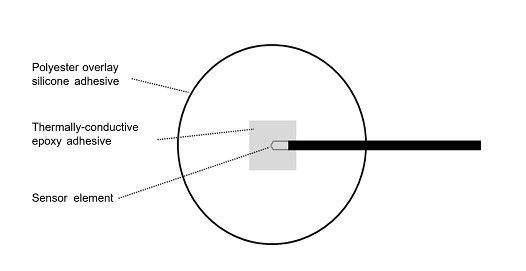
Figure 4 – Sensor attachment, permanent
Temporary (see Figure 5):
Trim thin-film sensor encapsulation (such as tape) to within approximately 3 mm of the sensor element. Round all trimmed corners.
Apply the sensor element to the centre of a round polyester adhesive dot or rounded polyester tape on the adhesive side. Tapes and dots fabricated with silicone adhesive are recommended. The sensor should stick to the tape.
Place the sensor element in the selected location. Manipulate the sensor to remove air bubbles.
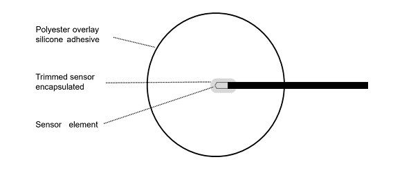
Figure 5 – Sensor attachment, temporary
Secure the sensor wire to the module’s backsheet using polyester tape at 2 to 4 points to reduce strain on the sensor element (see Figure 6). Generally, tape sections will not need to exceed approximately 2 cm wide by 5 cm in length. Use as little tape as possible to secure the lead wires.
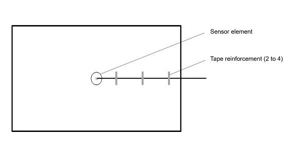
Figure 6 – Sensor element wire strain relief
For RTDs or thermistors, the measurement circuit may require a completion resistor. In this case select a resistor with a low temperature coefficient, e.g. ≤ 10 parts per million per °C.