In automation systems and industrial environments, ensuring that communication operates reliably, continuously, and without interruption does not depend only on correctly configuring device parameters; it also depends on the physical and electrical characteristics of the cable used.
Since the most common physical layer used in Modbus RTU communication is RS-485, what is commonly referred to in the field as a “Modbus cable” is actually a communication cable suitable for RS-485 topology.
Incorrect cable selection can cause serious problems such as CRC errors, communication interruptions, devices appearing offline intermittently, corruption in data packets, and unstable operation especially over long distances. Therefore, in RS-485 communication lines, the cable type, impedance, shielding, topology, conductor cross-section, grounding against noise, and extension methods must all be evaluated together.
The Relationship Between Modbus and RS-485
First, the meanings of these two terms must be clarified: Modbus is a communication protocol, while RS-485 is a physical transmission standard. In other words, Modbus defines the rules for data exchange between devices; the RS-485 communication standard determines how the physical properties of the cable should be.
Therefore, the technical answer to the question “What should a Modbus communication cable be like?” is essentially the same as the answer to “How should a cable suitable for the RS-485 communication standard be selected?”
Basic Characteristics of an RS-485 Communication Cable
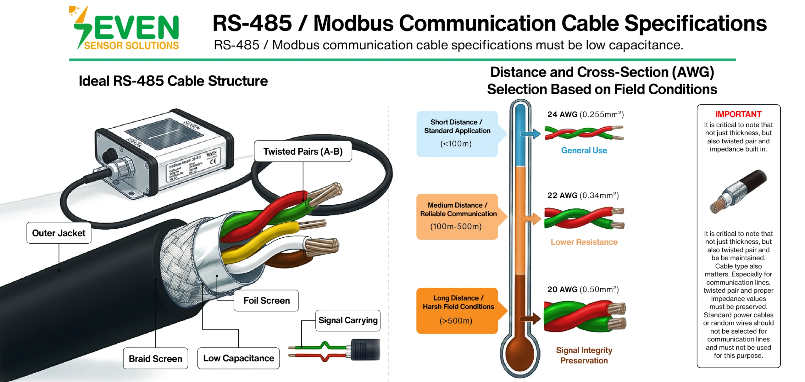
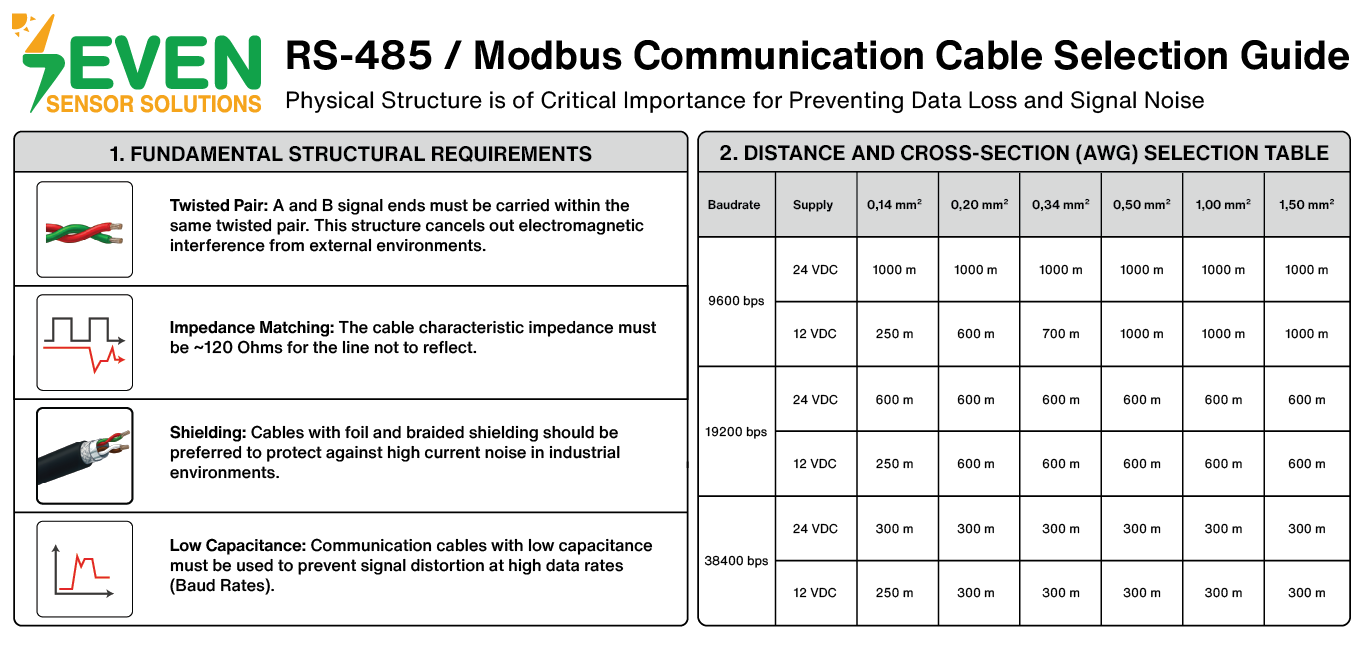
A cable used in an RS-485 communication line must have certain basic characteristics. One of the most important is the twisted pair structure. The A and B differential signal lines must be carried within the same twisted pair. The twisted structure ensures that electromagnetic interference from the environment affects both conductors similarly, and thanks to the differential communication principle, most of this noise is cancelled.
Another critical characteristic is the characteristic impedance of the cable. The impedance of an RS-485 cable should be approximately 120 Ohms. The 120 Ohm termination resistors placed at both ends of the line are also selected according to this impedance. If the cable used along the line does not meet this requirement, signal reflections may occur, leading to communication errors or loss of communication.
Another important factor is that the cable should have low capacitance. As capacitance increases, signal edges become distorted, data transitions weaken, and communication becomes less stable, especially at higher baud rates. Therefore, low-capacitance communication cables should be preferred.
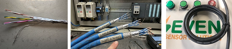
In industrial environments, using shielded cables provides a significant advantage. Motors, contactors, drives, inverters, and power cables carrying high currents generate considerable electromagnetic noise. For this reason, shielded cables, preferably with both foil and braid shielding, are recommended for RS-485 lines. This helps prevent noise generated by high currents.
Additionally, the conductor material should be copper, preferably tinned copper. Copper-clad aluminum conductors are not reliable in long-distance and critical communication applications due to their higher resistance.
Why Is Cable Cross-Section Important?
There is an inverse relationship between conductor resistance and cable cross-section. As the cross-section decreases, the conductor resistance increases. When resistance increases, signal attenuation may occur over long distances. In RS-485 communication lines, this becomes more noticeable because low-level differential signals are transmitted.
If the differential voltage seen by the receiving device drops below the required threshold level, data errors, communication faults, packet corruption, and CRC alarms may occur.
However, an important point should be noted: in RS-485 communication, cable diameter alone is not the determining factor. Other cable characteristics such as twisted pair structure, appropriate characteristic impedance, low capacitance, shielding, correct network topology, proper placement of termination resistors, and selecting baud rates appropriate for the distance are just as important as the cable cross-section.
Therefore, the assumption that “thicker cable is always better” is technically incorrect. The correct approach is to select a communication cable that complies with the RS-485 standard and determine its cross-section based on the application distance and field conditions.
Suitable Cable Cross-Sections for RS-485
According to general and reliable practices in the field, shielded twisted pair cables with a cross-section of 24 AWG, approximately 0.20–0.25 mm², are sufficient for most short-distance applications. These cables are widely used in short-distance systems.
For medium-distance applications, especially in systems over 100 meters, 22 AWG cables, approximately 0.34 mm², provide more reliable results. This cross-section reduces line resistance and improves signal integrity. It can also provide more stable operation in noisy environments.
For longer distances, especially 500 meters and above, 22 AWG remains a good choice. In more demanding field conditions, or to further reduce signal losses and ensure reliable communication, 20 AWG cables, approximately 0.50 mm², may be preferred.
However, simply increasing cable thickness is not sufficient at this point; the communication speed should also be reduced, and if necessary, the use of repeaters should be considered.
Frequently Asked Questions (FAQ)
Are Modbus cable and RS-485 cable the same thing?
Not exactly. Modbus is a protocol, while RS-485 is a physical transmission standard.
What is the most important structure in an RS-485 cable?
The twisted pair structure.
What should be the characteristic impedance of an RS-485 cable?
Approximately 120 Ohms.
Why is cable cross-section important?
As the cross-section decreases, resistance increases and signals may weaken over long distances.
Can star topology be used?
Absolutely not. An RS-485 line must be arranged in a Daisy Chain topology. In a star topology, signal reflections from each branch disturb the main line and cause unstable system operation.