Manual Soiling Sensor with HMI-PLC Monitoring
SEVEN Soiling Sensor is designed to measure the loss of energy production due to pollution caused by environmental
factors in photovoltaic modules. The Soiling sensor, which is suitable for commercial, utility, industrial and rooftop
projects, notifies the user of production losses due to pollution. If soiling level read from the sensor is 10%, it means that
there is 10% energy loss in the facility.
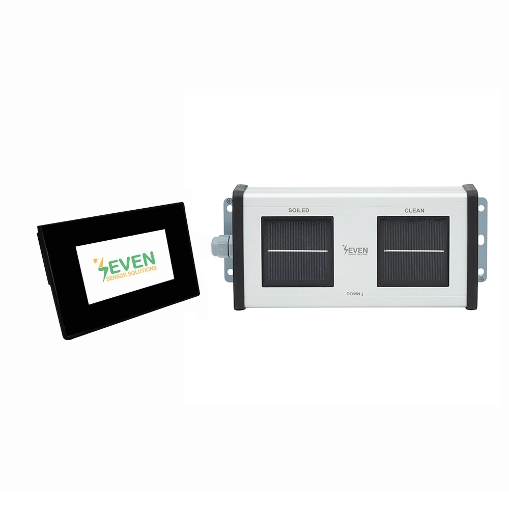
SEVEN Soiling Sensor calculates the soiling level of the PV system by comparing the irradiance values received from
the two clean and dirty irradiance sensors. While the dirty irradiance sensor in the system is exposed to contamination
in the same way as the panels, the clean irradiance sensor is cleaned manually by the user with a wet cloth. The data received from the Manual Soiling Sensor can be monitored by PLC.
TECHNICAL SPECIFICATIONS
| Item Code | 3S-SMS-HMI-M |
| Soiling Ratio | 0% – 100% |
| Resolution | 0,1% |
| Uncertainty | ≤1% |
| Irradiance | 0…1600 W/m² |
| Followed Standard | IEC61724-1 (Annex C) |
| Display Device | HMI Display (55 mm x 96 mm) |
| Operating Temperature Range | -40°C to +85°C |
| Operating Humidity Range | 0 to 100% |
| Power Supply | 12 to 30 V DC |
| Power Consumption | 15 mA @ 24 V DC |
| Electrical Connection | 3 m LIYYC11Y PUR Cable, UV and weather resistant |
| Galvanic Isolation | 1000 V between power supply and RS485 Bus |
| IP Rating | IP 65 |
| Dimensions | 244 mm x 108 mm x 42 mm (W x L x H) |
| Weight | 500 g |
| Calibration | Each sensor is calibrated and normalized under Class AAA Sun Similator as per IEC 60904-2 by using a reference cell calibrated by ISFH-Germany |
| Test | Each sensor is tested under natural sunlight by using a calibrated reference cell from Fraunhofer ISE, Germany.) |