Seven sensors are devices that can communicate with intermediary equipment via the Modbus RTU communication protocol. At this point, users have the ability to create additional monitoring systems.
So, what are these additional monitoring systems?
Our customers can not only read and monitor Seven sensors through a datalogger, but they can also transmit this data to different systems (e.g., SCADA, etc.). Data transmission is achieved by establishing a connection between the datalogger and the target system via the TCP/IP protocol.
The integration of our sensors into the datalogger is carried out in accordance with our specific Modbus maps, allowing sensor data to be read through the datalogger. The datalogger, in turn, can transmit this data to other systems using its own Modbus mapping structure.
As an example, we will explain this process through TCP/IP data transmission using a Huawei datalogger.
How is TCP/IP Data Transmission Achieved with a Huawei Datalogger?
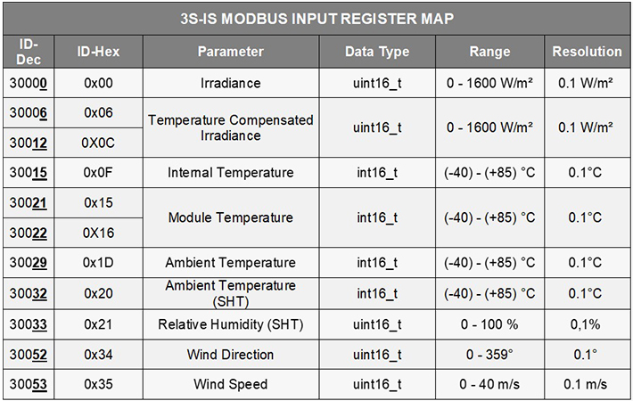
SEVEN Sensor Modbus Map
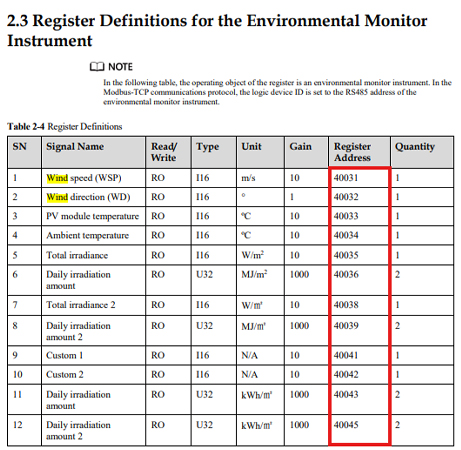
Huawei Modbus Map
How is the system configuration performed when using a datalogger?
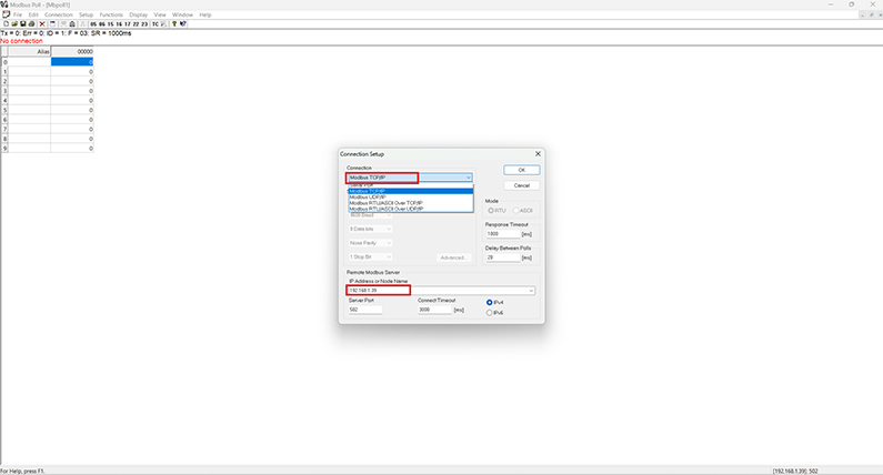
In this section, we will explain the configuration process using Modbus Poll and how to establish the TCP/IP connection with the datalogger in a simple way.
First, you need to know the IP address of the datalogger to which the sensor or sensor set is connected.
So, how can you find the IP address?
You can find both the IP address and the serial number of your datalogger on the label located on the physical housing of the device.
Alternatively, you can contact Huawei Technical Support with the serial number of your datalogger to obtain the Enspire interface login credentials.
(If you would like to learn more about configuring Huawei dataloggers for use with Seven sensors, please refer to the video titled “Huawei SEVEN Sensor Configuration” available on our official website or YouTube channel.)
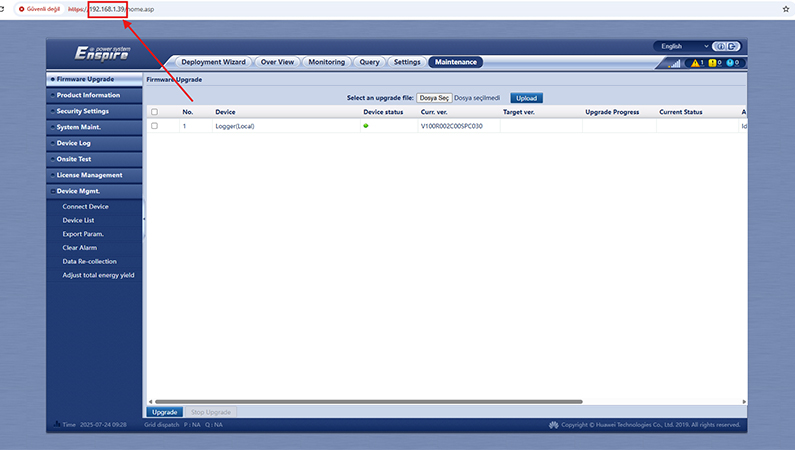
Once the IP address of the datalogger is obtained, the corresponding system interface is opened and the connection type is selected. The datalogger is then registered and configured within the system.
The specific sensor parameters needed for data transmission—such as sensor ID, register addresses, and data types—are determined.
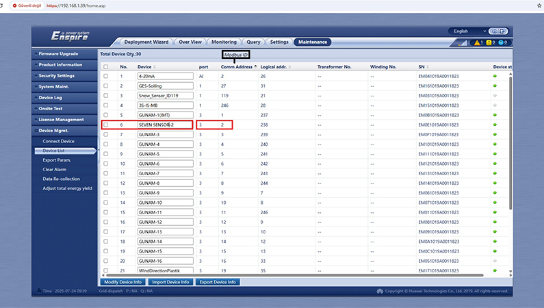
The corresponding sensor ID is defined. Then, the addresses to which the datalogger will transmit data are entered.
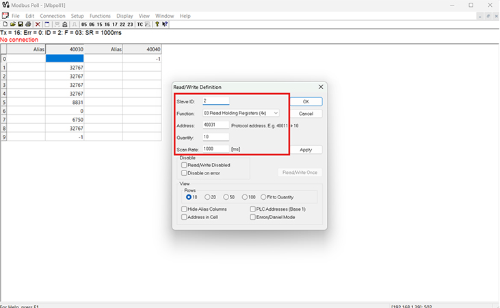
(In our example application, we demonstrated these steps using the Modbus Poll software; therefore, we showed how to define the starting register address and specify the number of registers to be read.)
After the configuration is completed, a connection can be established to read data, and the retrieved data can be verified through the datalogger interface.
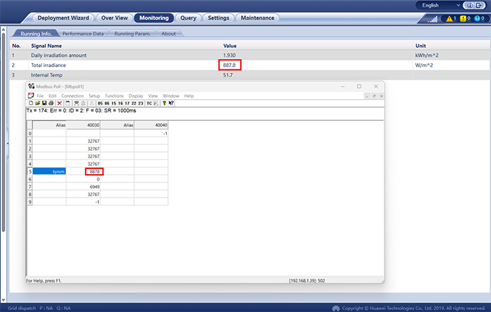
The logic of reading data on the relevant system by communicating via TCP/IP with the datalogger can be summarized as described above. If you need assistance with any topic, please feel free to contact our Technical Support Department.