Daisy chain connection is a method of connecting many electronic devices or modules in series. In a daisy chain connection, each device both receives and transmits data; thus, communication continues until the device at the end of the chain.
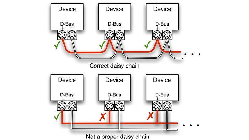
It has a 2-terminal connection port for communication via MODBUS. These terminals are mostly labeled as A [DATA +] and B [DATA -]. The wiring is done so that all these devices are connected in parallel. This means that all A terminals must be connected to each other, and all B terminals must be connected to each other.
This method is popular in sensor networks and data communication protocols because it:
- keeps wiring clean,
- scales easily (add another sensor without redesigning everything),
- improves stability when done with proper termination and grounding.
SEVEN offers the advantage of Daisy Chain connection, the easiest and best way to connect Modbus RTU – RS485 sensors.
How to Make a Daisy Chain Connection Between Sensors?
To establish a daisy chain connection between SEVEN sensors, the following steps are followed:
- Correct Sensor Selection
First of all, it should be known that SEVEN Sensor Solutions products are capable of being connected in series and addressable. These features are sufficient for a daisy chain connection.
- Use of RS485 or Similar Serial Communication Protocol
In daisy chain connections, RS485 is generally preferred as the physical layer between sensors since it provides reliable data transmission over long distances and in noisy environments. All SEVEN products have Modbus RTU RS485 communication capability.
- Use of Termination Resistor
120Ω termination is placed at:
- the first device/end of the line, and
- the last device/end of the line
Termination helps prevent signal reflections that can cause unstable readings, timeouts, or random communication errors.
- Address Assignment
Each SEVEN sensor must have its own unique address (between 1 and 247) so the master device can query the right sensor. If the daisy chain connection is requested during purchase stage SEVEN Sensor will perform the ID change for you.
Note: Line topology is preferred. Star or ring topologies are not suitable for the daisy chain concept.
What are the Important Considerations When Creating a Daisy Chain Connection?
- Cable Length: The total RS485 cable length should not exceed 1200 meters.
- Baud Rate: A lower baud rate is preferred over long distances (e.g., 9600 bps).
- Grounding and Protection: Proper grounding of the line and devices must be ensured. In SEVEN Sensor Solution products, sensors must be properly grounded using the black wire.
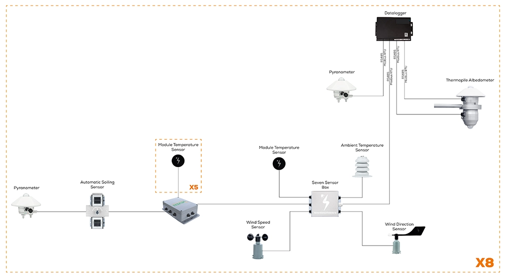
Sample Daisy Chain Connection Diagram Prepared by SEVEN Sensor Solution
Why Are Other Topologies Not Recommended?
Any other way of interconnecting devices is not recommended as it may cause communication problems or damage the entire system. Connection diagrams that are not recommended are included below.
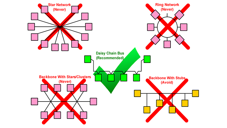
Master/Slave Device Connection Not Recommended
Why is Star Network Risky?
All sensors are directly connected to one central node. This is how problems can arise:
- If the central point fails, the whole system crashes (single point of failure).
- It is particularly unsuitable for sensor systems spread over large areas.
- It creates difficulties in terms of time synchronization and data integrity.
- Cable length increases and communication problems may arise accordingly.
Why is Ring Network Risky?
The sensors are connected together in a ring. Problems can arise with this method as follows:
- If any connection breaks, the data in the whole ring is corrupted.
- Data delays are high; data has to travel around the entire ring.
- Error detection and repair is complex.
Why is Backbone with Stars/Clusters Network Risky?
It is a model where sub-star and cluster structures are connected to a network of communication lines. Problems can arise in this model as follows:
- Multiple central nodes are created and each of them is a potential point of failure.
- Again, the risk of “single point of failure” increases.
- Synchronization becomes difficult and network complexity increases.
Why is Backbone with Stubs Risky?
There are sensors connected to the main communication line via short branches. Problems can arise with this connection as follows:
- These short arms (stubs) cause signal reflections and noise.
- Load imbalance on the bus lines leads to data corruption over time.
- Poor fault tolerance and signal integrity problems.
Why Is Daisy Chain the Most Reliable Connection Method?
Daisy chain is the most accurate and reliable connection method for many RS485 sensor networks because it offers a structured line topology that supports stable communication.
Especially when used with Modbus RTU RS485, daisy chain wiring allows sensor networks to be built in an organized, reliable, and cost-effective way.
The quality of communication depends directly on:
- good wiring
- correct addressing
- proper termination
- correct grounding
In PV systems, daisy chain wiring provides important advantages for sensor installation and communication management.
SEVEN Sensor Solution can prepare all the sensors you need to be compatible with daisy chain connections and meet your requirements. You can contact SEVEN Sensor Solution via the following link: “ https://www.sevensensor.com/contact ”.
FREQUENTLY ASKED QUESTIONS (FAQ)
What does “daisy chain” mean for Modbus RS485?
It means wiring devices in a line (bus) topology where all sensors share the same two communication wires: A (DATA +) and B (DATA -).
What is the use of a termination resistor in daisy chain connection?
Termination helps prevent signal reflections that can cause unstable readings, timeouts, or random communication errors.
Do I need a termination resistor on every sensor when connected in daisy chain?
No. Typically you use 120Ω termination only at the two ends of the RS485 line.
What happens if I wire RS485 in a star topology?
Star wiring often creates reflections and signal issues, leading to unstable communication—especially as cable length increases.
How many sensors can I daisy chain?
It depends on network design (device load, cabling, baud rate, and transceiver limits). Practically, you’ll plan based on stable communication first, then scale while keeping the topology clean and properly terminated.
Does baud rate matter for long cable runs?
Yes. Lower baud rates are generally more reliable over long distances (for example 9600 bps).
Does ID matter for daisy chain connection?
Each sensor must have its own unique address (between 1 and 247) so the master device can query the right sensor.
What happens if grounding is done incorrectly?
Improper grounding can reduce communication reliability and may cause signal instability or device-related issues.
Why is RS485 commonly used in daisy chain networks?
RS485 is preferred because it supports reliable communication over long distances and performs well in noisy industrial environments.