Proper grounding is crucial for the proper and stable operation of sensors in industrial automation systems. Incorrect or inadequate grounding on the sensor side can lead to measurement errors, data transmission disruptions, and in some cases, damage to the equipment.
So what are these “proper ground” connections that we constantly hear about and emphasize at SEVEN? In this article, we will examine ground connections.
What is Grounding?
In an electrical or electronic system, grounding is an important connection that ensures any leakage currents and electromagnetic interference are safely transferred to the ground. This allows the system to operate more safely and reliably.
Grounding in electrical systems is performed for three main purposes:
- To ensure safety
- To reduce electrical noise
- To create a reference potential
In sensor applications in particular, proper grounding helps ensure more consistent and accurate measurements. It also contributes to smoother system operation by keeping the signal more stable.
Is Grounding Important in Sensor Systems?
Sensors often produce very low level signals. Therefore, even the slightest electrical noise in the system can affect the measurement and cause errors.
Proper grounding:
- Reduces noise
- Increases measurement accuracy
- Prevents communication errors
- Ensures equipment safety
Grounding is particularly critical in the following systems:
- Industrial sensor networks
- PLC systems
- Analog sensors (4-20 mA, 0-10V)
- RS485 / Modbus communication lines
- IoT sensor applications vb.
What Are the Types of Grounding?
In sensor systems, the “ground/0V reference” is often taken from a common point. The critical issue, however, is how this reference is distributed throughout the system. This is because there are several different grounding approaches used in sensor applications, depending on specific requirements.
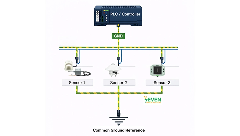
1. Common Ground
This is not a connection type, but rather means that all devices share the same 0V/GND reference. In practice, this common reference is usually collected at a single point on the panel and distributed.
Advantages: simple setup, working with the same reference, low cost, compatible and stable measurement infrastructure, etc.
Thanks to this structure, all sensors use the same reference voltage. Common ground generally gives the best results when implemented with star grounding.
2. Star Grounding
The 0V/GND line of each sensor is connected separately to a single common point on the panel.
Advantages: Noise – Less interference, reduced risk of ground loops, increased measurement accuracy and stability.
It is one of the most recommended methods in industrial automation systems.
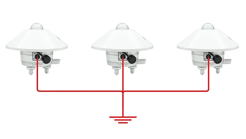
3. Daisy Chain Grounding
This method is similar to a daisy chain connection. You can find more information about daisy chain connections here. The 0V/GND line, i.e., the ground connection, is transferred from sensor to sensor.
Advantages: Less cabling is required, and installation is quick.
Disadvantages: Noise from each device can be transferred to others, measurement errors or fluctuations may occur, and there is a possibility of ground loops.
Recommended for use in small systems and environments with low noise levels. However, it is not highly recommended for measurements in critical and large systems.
What is a Ground Loop?
A ground loop is an unwanted current loop that occurs when multiple ground paths exist in a system.
This situation can lead to the following problems:
- Analog measurement errors
- Fluctuations in sensor data
- Communication errors
- Electrical noise
To prevent ground loops, single-point grounding is generally preferred. The cable shield should not be grounded at each device, but only at a single point.
Important Considerations When Grounding Sensors
For correct and trouble-free grounding in sensor systems, particular attention should be paid to the following points:
1. A common reference point should be used.
Connecting all sensors to the same GND/0V reference ensures more consistent measurements.
2. Ground loops should be avoided.
Connecting a device to ground at multiple points can cause circulating currents, leading to noise and measurement errors.
3. Cable shielding must be connected correctly.
When using shielded cable, grounding the shield at one end usually yields better results (grounding at both ends can sometimes increase noise).
4. Power and signal cables should be separated.
Motors, drivers, and high-current lines can cause interference if they run close to sensor cables. Therefore, they should be routed separately whenever possible.
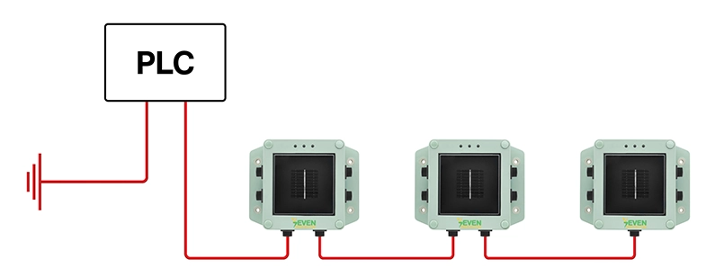
How to Make the Correct Ground Connection Between Sensors?
When grounding sensors, a common reference point (common ground) is often established.
The logic is quite simple: the GND terminals of all sensors are connected to the same reference point; thus, all sensors use the same “0V” level as a base.
The connection between sensors is usually made as follows:
- The GND output of the sensor is taken.
- It is connected to the GND line of the PLC or control card.
- The entire system uses a common ground reference.
In a PLC system, the sensor connection may be as follows:
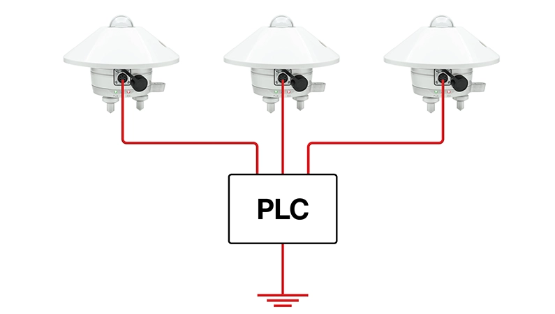
Thanks to this structure:
- Sensors operate stably.
- Noise is minimized.
- Measurement errors are reduced.
How to Properly Ground a Modbus RS485 Communication Line?
- Use a daisy chain connection. For detailed information… The data line should not be connected in a star configuration.
- A 120Ω termination should be added to both ends of the line (Start-End).
- Shielded cable should be used.
- The shield should be grounded at a single point.
- A signal ground (GND) line should be added for long distances.
Therefore, in Modbus communication, using a Daisy Chain for the data line and a Star (single-point) ground connection is the most stable solution in the industry.
In sensor networks, a common grounding approach is often used; to distribute this common reference more consistently and smoothly, a star connection is most frequently preferred. Daisy chain grounding may be useful in some scenarios, but it must be carefully planned due to risks such as interference and reference drift.
Grounding is truly a fundamental issue for the safe and accurate operation of sensor systems. Properly designed grounding improves measurement accuracy, reduces electrical noise, and increases overall system safety.
SEVEN Sensor Solution can prepare all the sensors you need to be compatible with ground connections and meet your requirements. You can contact SEVEN Sensor Solution here.
Frequently Asked Questions (FAQ)
What happens if there is no ground connection in the sensors?
If the grounding is incorrect, the sensor may be affected by interference. This can cause incorrect measurements, fluctuating values, or system malfunctions. In some cases, communication problems and device failures may also occur.
How should the ground connection be made between sensors?
The most practical and safe method is to connect all sensors' ground/0V lines to a single common point. In other words, instead of connecting the sensors to each other like a chain, it is healthier to connect them all to the same ground (or 0V) point specified on the panel.
Where should the shield of the shielded cable be connected?
Generally, the shield is connected on one side only. This is usually the panel/PLC side. Connecting it on both sides can sometimes increase interference. Therefore, connecting it on one side is safer in most applications.