In applications that require extending Modbus communication – RS485 – cables, the first issue to consider is that the added cable must have the same characteristics and properties as the existing line. That is, the cable used for extension must also strictly comply with RS-485 topology, be shielded, twisted pair, and have an impedance of approximately 120 Ohms.
Generally, a 24 AWG cross-section is mostly sufficient for short-distance extensions. However, as the total line length increases, switching to a cable with a larger cross-section will be healthier to obtain better measurements. If the line is long and in applications with electrical interference, 20 AWG cables should be preferred. In addition, without looking at the other properties of the cable, it is not suitable to use any power cable in the communication line just because its diameter is large. Because power cables do not provide the required impedance and capacitance values that should be in a communication cable. Although they are thick, they may not provide healthy Modbus communication.
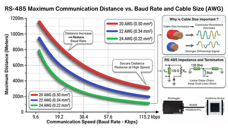
Briefly, the points to consider when selecting a cross-section to extend cables on lines communicating with RS485 are;
- A cable suitable for Modbus communication should be selected.
- The total distance should be calculated, and field conditions should be evaluated.
- Based on this information, 24 AWG, 22 AWG, or 20 AWG cable thicknesses should be evaluated.
Meteorological weather observation stations that we produce under the Seven Sensor brand communicate with the Modbus protocol. In the communication lines of the sensors, attention should be paid to the specified criteria in order to avoid problems in data transmission and communication. For more detailed information, you can contact our technical team.
Relationship Between Maximum Distance and Baud Rate
In Modbus communication cables, the theoretical maximum communication distance is 1200 meters. There are some other technical specifications that affect the actual distance. Some of these are; Baud rate, impedance, capacitance, cross-section of the cable, number of devices, topology structure, and termination resistor.
In Modbus communication, there is an inverse proportion between cable length and baud rate. As the distance increases, the baud rate must be reduced. While long cable length is possible at low data rates, reliable communication drops significantly when high speed is requested. For this reason, in Modbus communication applications, attention should be paid not only to the cable cross-section, but also to the communication speed.
Topology Selection and Connection Type
If you have more than one sensor in your field and if they communicate with Modbus, the RS-485 line must definitely be established in a linear structure along the line, that is, in a daisy-chain topology. https://www.sevensensor.com/what-is-daisy-chain-connection-how-to-make-daisy-chain-connection-between-sensors
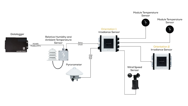
Making a star connection in such applications is one of the most common mistakes. Star connection topology causes signal reflections, significantly impairing communication, especially over long distances.
Short drop connections (Stub lines) subsequently connected to the main line should be kept as short as possible. As the stub line length increases, the communication quality drops. Therefore, device connections to the main line should be as short as possible.
Termination Resistors
There must be a termination resistor at either physical end of the Modbus communication line. It is used to reduce signal reflections, prevent data corruption, reduce noise, and ensure stable operation of the line. Termination resistor is not applied to every device; it is applied only to the start and end points of the line. Additionally, using excessive resistors can also negatively affect the operation of the communication line.
Shielding and Earthing
How to earth the shield in shielded cables is important. Earthing the shield from a single point is accepted as general knowledge. Most of the time, the earthing process is performed by PLC or “master” device. Earthing the shield from both ends causes “ground loop” if there is a potential difference between different panels. This situation can cause instability in communication.
Signal Ground Usage
Using a signal ground line may vary depending on each specific application. For example, while connecting A and B leads is sufficient in some applications, using a signal ground or a “common” line for devices with potential differences between them increases communication stability. This detail is especially important in systems distributed across different panels.
Things to Consider in Cable Splices
Splices made during cable extension should be solid, short, and neat. The polarity of both ends and the matching of two devices in the same way should be preserved as much as possible. Loose joints, oxidized connections, and shield continuity must be maintained. The entirety of the cable to be used on the same line must be selected as a cable suitable for Modbus communication. Piece-by-piece cables with different characteristics used on the line disrupt the impedance balance and cause communication problems.
Power Cable Should Not Be Mixed With Communication Cable
Depending on the application, the data line and power supply line may be inside the same cable. Again, depending on the application, the cross-section requirements for the data line and power line may be different. In such cases, separate cable cross-sections should be determined according to the project’s needs and applied accordingly.
Common Mistakes Made in the Field
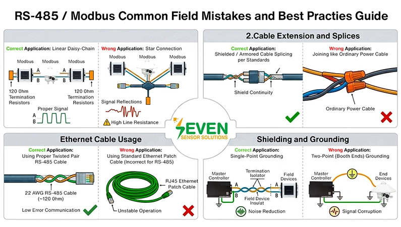
One of the common mistakes seen in RS-485 communication applications is using an Ethernet cable by splicing it as a communication cable in long-distance lines. Although some systems work at short distances, Ethernet cables do not have the required impedance (120 OHM), so they are not an ideal solution for long-distance cable applications. As Seven Sensor, using Ethernet cable as a communication cable for both short and long distances is not recommended.
Another common mistake is using a star connection topology when running multiple sensors over a single line. In applications like this, the daisy chain connection method must be used. In addition, long stub connections, earthing the shield from both ends, using ordinary power cables in the communication line, and applying more termination than necessary are also problems frequently encountered in the field.
Conclusion
Proper cable selection is one of the basic characteristics required for RS485/Modbus communication to operate reliably and stably. Other sought-after features are; the cable being twisted pair, shielded, having 120 Ohm impedance, low capacitance, and preferably copper conductor.
Cross-section selection in the cable should be made according to distance and field conditions. 24 AWG is preferred for short distances, 22 AWG for medium distances. 20 AWG cable, on the other hand, is preferred in long and harsh condition applications. In addition to the cable cross-section diameter, other technical specifications are also important. Correct topology, suitable termination resistor, shielding, and appropriate baud rate selection according to distance are important for successful Modbus communication.
In cable extensions, the basic rule is first to select a cable suitable for the Modbus standard, then to determine the appropriate cross-section according to total line length and field conditions.
Frequently Asked Questions
What type of cable should be used for RS-485 extension?
It should contain the characteristics of a Modbus communication cable. It must be a communication cable suitable for RS-485 standards, shielded, twisted pair, and having an impedance value of 120 Ohms.
How should the cable cross-section (AWG) be selected as the distance increases?
Short distances: 24 AWG is generally sufficient.
Medium/Long distances: 22 AWG should be preferred.
Industrial noisy/Very long lines: 20 AWG offers a healthier performance.
Can standard power cables be used just because they are thick?
No. Power cables do not provide technical features such as the required impedance and capacitance values, and because they degrade signal quality despite being thick, they should not be used in Modbus communication systems.
What is the maximum communication distance and how does it affect speed (Baud Rate)?
The theoretical limit is 1200 meters. There is an inverse proportion between distance and baud rate; as distance increases, the baud rate (communication speed) must be reduced to prevent signal loss. High baud rates are safe only over short distances.
Which topology should be used when connecting multiple Modbus devices?
The RS-485 line must strictly be established in a Daisy-Chain, that is, linear structure. Star topology should strictly be avoided as it causes signal reflections. https://www.sevensensor.com/what-is-daisy-chain-connection-how-to-make-daisy-chain-connection-between-sensors
Is Ethernet cable (Cat5/Cat6) suitable for RS-485?
Although it works over short distances, Ethernet cables generally have an impedance of 100 Ohms. It is not ideal for long-distance and professional solutions.