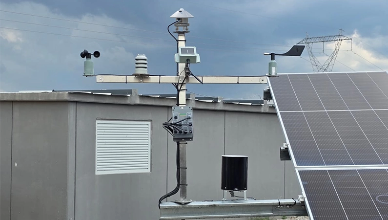
1. GENERAL PROVISIONS
1.1. Definitions, Abbreviations and Standards
1.1.1. Definitions
The fundamental terms used within the scope of this specification are defined as follows:
Sensor: Refers to a measurement device that measures an environmental or performance-related physical quantity at the PV plant site and transmits this data to the data acquisition system.
SCADA: Refers to the centralized control and data acquisition system that collects data from sensors and field equipment, monitors, records, and provides higher-level supervision.
Data Logger: Refers to the data acquisition device that collects data from sensors at defined time intervals, records it, and transmits it to upper-level systems when required.
Calibration: Refers to the process of verifying and, if necessary, adjusting a sensor’s measurement output against a traceable reference.
Verification: Refers to the process of confirming that the sensor provides the expected measurement performance in the field.
Investor’s Representative: Refers to the person or entity authorized by the investor to review, approve, inspect, and verify compliance with this specification.
Uncertainty: Refers to the range of deviation of the measurement result from the true value.
Resolution: Refers to the smallest measurement change that the sensor can distinguish.
Azimuth: Refers to the horizontal directional orientation of the sensor or the PV module plane.
Tilt (Inclination Angle): Refers to the angle of the sensor or PV module plane relative to the horizontal.
Albedo: Refers to the ratio of reflected irradiance from a surface to the incident irradiance upon that surface.
Daisy Chain: Refers to a connection structure in which multiple devices are connected in series on the same communication line.
1.1.2. Abbreviations
This section provides the abbreviations used in the technical terms and expressions within the scope of this specification, along with their definitions.
AC: Alternating Current
ABS: Acrylonitrile Butadiene Styrene
ASA: Acrylonitrile Styrene Acrylate
AWG: American Wire Gauge
DC: Direct Current
ESD: Electrostatic Discharge
EFT/Burst: Electrical Fast Transient / Burst
PV: Photovoltaic
PV Plant: Photovoltaic Power Plant
GHI: Global Horizontal Irradiance
HMI: Human Machine Interface
IP: Ingress Protection
I²C: Inter-Integrated Circuit
Modbus RTU: Modbus communication protocol based on Remote Terminal Unit
O&M: Operation and Maintenance
POA: Plane of Array
PR: Performance Ratio
PT1000: Platinum temperature sensor with 1000 ohm nominal resistance
PUR: Polyurethane
RH: Relative Humidity
RTD: Resistance Temperature Device
RTU: Remote Terminal Unit
SCADA: Supervisory Control and Data Acquisition
SPD: Surge Protective Device
SunSpec: Standard data model for solar energy equipment
UV: Ultraviolet
1.1.3. Standards and Reference Documents
Unless otherwise specified, the sensors, equipment, installation practices, calibration procedures, and performance evaluations to be used within the scope of this specification shall comply with the latest versions of the following standards.
The international standardization organizations are listed below:
- ISO International Organization for Standardization
- IEC International Electrotechnical Commission
The main standards belonging to these organizations and used within the scope of this specification are listed below:
IEC 61724-1
Serves as the basis for measurement requirements, sensor accuracy classes, data acquisition and quality criteria, monitoring of environmental parameters, and performance evaluation methods for photovoltaic systems.
IEC 60904-2
Serves as the basis for the characteristics and calibration requirements of PV reference devices.
ISO 9060
Serves as the basis for the classification and performance criteria of pyranometers.
ISO 9847
Serves as the basis for the calibration methods of pyranometers.
IEC 60751
Serves as the basis for the accuracy classes of PT1000 type platinum resistance thermometers.
ISO/IEC 17025
Serves as the basis for the competence and accreditation requirements of calibration laboratories.
IEC 62548
Serves as a reference for PV system installation and field applications.
1.2. Scope
The purpose of this document is to define the technical requirements to ensure that all sensors measuring environmental parameters used in Photovoltaic Power Plants (PV Plant) are selected, installed, calibrated, and operated in accordance with international standards. The accuracy, traceability, and reliability of the data obtained from sensors are of great importance for the evaluation of PV plant performance, generation of energy yield estimates, fault detection, identification of performance losses, and operational optimization.
This document, which is a draft specification, covers the following sensors:
- Irradiance Sensor — Referred to as a Reference Cell or PV Pyranometer and used for plane of array (POA) measurements
- Pyranometer — Used for Global Horizontal Irradiance (GHI) measurements
- Module Temperature Sensor
- Ambient Temperature Sensor
- Humidity Sensor
- Wind Speed Sensor
- Wind Direction Sensor
- Albedometer — Measures the irradiance (POA) incident on both sides of bifacial modules and calculates the ratio
- Soiling Sensor — Measures the energy loss caused by contamination on the module surface
- Rain Gauge
- Snow Sensor — Calculates the energy loss caused by snow accumulation on the modules
1.3. Purpose
The primary purpose of using these sensors in PV plant projects is to calculate the Performance Ratio (PR) of the facility. This ratio is calculated in accordance with the IEC 61724-1 standard. Even if some sensors are not directly involved in the calculation, they are used in the interpretation and evaluation of the resulting PR value.
Performance Ratio (PR): Defined as the ratio of the actual AC energy output obtained from the PV plant to the theoretical energy production calculated based on the irradiance incident on the module plane (POA) and the nominal installed capacity of the system. PR calculation can be performed for different time periods. The formula below is taken from the IEC standard for PR calculation.
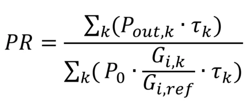
As seen in the formula, only irradiance (POA) and module temperature data obtained from sensors are used. No other sensor data is directly included in the formula. However, a PR evaluation based solely on irradiance and module temperature data would be quite limited. The measurement of other environmental parameters is used to understand and interpret variations in PR. For example, if a decrease in the PR value is correlated with a high value from the soiling sensor, the cause of this decrease may be attributed to contamination. If no such condition is observed in the soiling sensor, then other sensor data shall be examined. If the data from all sensors do not explain the performance degradation, then the plant equipment (inverter, modules, cables, etc.) should be inspected and the root cause of the degradation should be investigated.
Sensor data cannot directly identify which equipment is causing the problem, but it reveals the existence of an issue in the plant through the PR value. If the PR value falls below its expected level and there is no sensor data to explain this decrease, it indicates a problem with the plant equipment. Recognizing the existence of a problem is the first step toward its resolution. In summary, the primary purpose of using sensors in PV plant projects is to calculate and evaluate plant performance.
This document defines all technical requirements from sensor selection to installation, and from operation to maintenance and calibration cycles, and establishes the minimum quality standards that shall be met by the contractor. With this draft specification, it is aimed to improve the reliability of long-term performance monitoring data in PV plant projects, to ensure transparent tracking of system losses, and to establish a measurement infrastructure compliant with international financing and auditing requirements.
1.4. Sensor Selection in Compliance with Environmental Conditions
Within the scope of this draft specification, the selection of sensors to be used in Photovoltaic Power Plants (PV Plant) shall consider the site conditions and external environmental factors of the installation location. Sensors shall have sufficient mechanical strength, temperature tolerance, and humidity resistance to ensure long-term operation in accordance with the climatic characteristics of the region where they are installed. These criteria shall be considered during plant design and equipment selection and shall be explicitly specified in the relevant project specification.
The types of installation sites include terrestrial locations, desert-like regions with high temperatures, high-altitude areas, regions exposed to saline air, and floating PV plant applications. Therefore, the operating ranges of the sensors shall be specified in the project specification to ensure adequate resistance against external factors such as high temperature fluctuations, intense UV exposure, wind loads, snow loads, and soiling.
Since meteorological effects such as rain, snow, hail, high humidity, and condensation can directly affect sensor performance, it is essential that all meteorological and PV performance measurement sensors have an appropriate IP protection rating. While IP54 protection is generally sufficient against dust and water splashes in terrestrial installations, higher levels of water resistance (such as IP67, IP68) are required in floating PV plant applications due to the proximity or exposure of sensors to water.
In regions with cold climates, high altitudes, and frequent snow/ice formation, heated versions of certain components such as pyranometers, irradiance sensors, and wind speed/direction sensors may be required. Heated sensors prevent ice formation, dew accumulation, or snow layer buildup on the surface, thereby ensuring accurate measurements. In such sensors, heaters are typically thermostat-controlled and are automatically activated when the ambient temperature falls below a certain threshold.
Mechanical factors such as wind loads, variations in module tilt angles, vibrations in pole-mounted structures, and structural stability shall also be considered in the installation design. In addition, since heavy soiling and contamination may cause measurement errors, particularly in pyranometers and irradiance sensors, maintenance and cleaning intervals shall be planned based on environmental conditions, and preferably, sensors with automatic cleaning features should be selected.
Within this scope, the minimum protection levels and physical durability requirements to ensure the safe, stable, and long-term operation of sensors under environmental conditions shall be detailed in the following sections according to sensor types.
1.5. Documentation and Approval Process
The contractor is obliged to submit the technical documents, certificates, and drawings related to all sensors and associated equipment to be supplied within the scope of this specification to the investor.
The documents to be provided by the contractor shall include at least the following contents:
- Product technical data sheets
- Product installation manuals
- Electrical connection diagrams
- Communication protocol and configuration manuals
- Calibration certificates and laboratory accreditation certificate
- Data logger compatibility certificate
- Warranty documents
- Additional documents shall be provided depending on the sensor selection to be used in the plant. These documents are specified in the relevant sensor sections.
All documents submitted by the contractor shall be reviewed and approved by the investor or the Investor’s Representative. Document approval only confirms compliance of the content with the specification; it does not eliminate the responsibility for the performance, durability, or site suitability of the sensors.
In case the documents are incomplete, found to be non-compliant, or deemed technically insufficient by the investor, the investor shall request the contractor to make the necessary corrections. After the corrections are made, the documents shall be resubmitted for investor approval.
2. SYSTEM GENERAL REQUIREMENTS
2.1. Types, Classes, and Quantities of Sensors to be Used in the Field
Sensors to be used in PV plant sites shall be installed for the purpose of monitoring meteorological parameters and parameters related to PV performance, such as irradiance, temperature, wind, humidity, precipitation, and soiling. In determining sensor types and technical specifications, the IEC 61724-1 Performance Monitoring Standard shall be taken as the basis. This standard classifies performance monitoring systems according to accuracy levels and defines the technical requirements for irradiance sensors to be used in monitoring systems, particularly for Class A and Class B. In the table below, the irradiance sensor requirements specified in IEC 61724-1 are summarized for Class A and Class B monitoring systems.
In this table, two types of irradiance sensors are available, and one of them may be selected in accordance with the IEC 61724-1 standard.
PV Reference Cell type Irradiance Sensor is a relatively new technology (developed in the 2000s) that measures the solar irradiance incident on the module plane (Plane of Array — POA). It is designed according to the needs of PV installations. For example, it offers an economical solution by allowing multiple external sensors to be connected and transmitting data over a single Modbus line. Due to its photovoltaic structure, it exhibits the same characteristics and behaviour as solar panels.
Pyranometer is a much older technology (developed in the early 1900s) designed to meet meteorological measurement requirements and is specifically used for measuring GHI (Global Horizontal Irradiance).
This technological difference can result in a price difference of up to six times between the two products. The pyranometer is a well-known and widely used product in the industry for many years. The PV Reference Cell type Irradiance Sensor, on the other hand, is a relatively new product designed specifically for POA measurements in PV systems.
For this reason, it is considered appropriate to use a PV Reference Cell type irradiance sensor for POA measurements and a pyranometer for GHI measurements in PV plants. Therefore, the use of 1 pyranometer and 1 PV Reference Cell type Irradiance Sensor is recommended. Depending on the plant size and number of orientations, the number of PV Reference Cell type Irradiance Sensors may be increased.
| Sensor Type | Class A Monitoring System | Class B Monitoring System |
| Pyranometer | POA or GHI: According to ISO 9060:2018, a Class A (Secondary Standard) spectrally flat pyranometer shall be used. Calibration uncertainty ≤ 2% (1000 W/m²),
Measurement range ≥ 1500 W/m², Resolution ≤ 1 W/m². |
According to ISO 9060:2018, a Class C or better pyranometer shall be used.
Calibration uncertainty ≤ 3% (1000 W/m²),
Measurement range ≥ 1500 W/m², Resolution ≤ 1 W/m². |
| PV Reference Cell | A calibrated working reference sensor compliant with IEC 60904-2 may be used.
Calibration uncertainty ≤ 2% (1000 W/m²),
Measurement range ≥ 1500 W/m², Resolution ≤ 1 W/m². |
A working reference sensor compliant with IEC 60904-2 may be used.
Calibration uncertainty ≤ 3% (1000 W/m²),
Measurement range ≥ 1500 W/m², Resolution ≤ 1 W/m². |
Table 1: Sensor Accuracy Class Requirements in Accordance with IEC 61724-1:2021
Although a Class C monitoring level is also defined in the IEC 61724-1 standard, sensor types and technical requirements for this level are not provided in detailed tables as they are for Class A and Class B. The Class C monitoring level refers to monitoring applications with lower accuracy requirements, intended for basic performance tracking, and detailed sensor classifications and measurement uncertainties are addressed only to a limited extent within the scope of IEC 61724-1.
2.1.1. Number of Sensors
The number of sensors to be used in the field may vary depending on site characteristics such as plant capacity, land size, array layout, orientation, and tilt variations. The IEC 61724-1 Performance Monitoring Standard defines recommendations for sensor placement for Class A monitoring level; however, it does not provide a quantitative guideline for the number of sensors for other monitoring classes. In this context, the sensor quantities recommended for Class A according to IEC standards, based on site sizes in MW, are presented in the table below.
It is recommended to use at least two irradiance sensors. This is because, in cases such as sensor failure, data validation, and calibration processes, the availability of a backup sensor on-site is required; therefore, two irradiance sensors should be used.
| System Size (AC) | ||||||
| SENSOR TYPE | <40 MW | 40 MW≤ <100 MW |
100 MW≤ <300 MW |
300 MW≤ <500 MW |
500 MW≤ <700 MW |
700 MW≤ |
| PYRANOMETER | 2 units | 3 units | 4 units | 5 units | 6 units | 7 units, plus 1 unit per additional 200 MW |
| IRRADIANCE SENSOR (REFERENCE CELL) | ||||||
| ALBEDOMETER* | 6 units | 9 units | 12 units | 15 units | 18 units | 21 units, plus 3 units per additional 200 MW |
| MODULE TEMPERATURE SENSOR | ||||||
| AMBIENT TEMPERATURE SENSOR | 2 units | 3 units | 4 units | 5 units | 6 units | 7 units, plus 1 unit per additional 200 MW |
| HUMIDITY SENSOR | ||||||
| WIND SPEED SENSOR | ||||||
| WIND DIRECTION SENSOR | ||||||
| SOILING SENSOR | ||||||
| RAIN GAUGE | ||||||
| SNOW SENSOR | ||||||
*In bifacial module applications, a POA albedometer or a rear-side irradiance sensor (the irradiance sensor shall be installed with the same tilt angle as the rear side of the modules) may be used.
Table 2: Minimum Sensor Quantity Requirements by Installed Capacity (IEC 61724-1:2021)
Within the scope of this draft specification, all sensors will be explained in detail in the relevant sections, and the general approach regarding the sensor classes and quantities specified here aims to ensure compliance with measurement classes, sensor accuracy levels, and representativeness criteria defined in IEC 61724-1. The sensor layout plan shall be subject to a detailed site analysis to be prepared by the contractor and to the approval of the investor. The locations where the sensors will be installed in the field are highly important. Sensors shall be uniformly distributed across the site. Sensors of the same type shall not be concentrated at a single location. If there are 6 module temperature sensors, these sensors shall be distributed across all regions of the site at equal distances from each other.
2.2. Calibration Requirements
Sensors used especially for irradiance measurement shall definitely be delivered to the Investor’s Representative with calibration certificates. Calibrations may be performed in factory laboratories. However, these laboratories shall be accredited for at least one parameter in accordance with the ISO 17025 standard. Calibrations performed in a laboratory without any accreditation according to ISO 17025 shall not be accepted. This accreditation indicates the competence of the laboratory in calibration. The relevant document shall be submitted to the Investor’s Representative during the approval process of the sensors.
Calibration requirements for pyranometer, albedometer and other irradiance sensors are defined in ISO 9060 and IEC 60904-2 standards. Calibrations not performed according to these standards shall not be accepted. The periodic recalibration requirement for irradiance sensors used in Class A monitoring level is two (2) years.
In sites where the soiling level is high, temperature differences are significant, or UV exposure is intense, it is recommended that sensor performance be monitored more frequently with on-site verification checks.
There is no mandatory periodic recalibration requirement for temperature, wind, humidity, precipitation, and similar auxiliary meteorological sensors. These sensors shall be subjected to periodic calibration or verification with the intervals recommended by the manufacturer or depending on the investor’s preference. This period shall not be longer than 5 years.
Within the scope of on-site controls, the mechanical installation condition of sensors, installation angles, cable integrity, and physical cleanliness shall be checked weekly. If any abnormal conditions that may affect measurement performance are detected, corrective action shall be applied to the relevant sensor.
The contractor shall be responsible for documenting the factory calibration information of the sensors and, if any, the periodic calibration plan for irradiance sensors. Sensors whose calibration validity has expired or that cannot ensure measurement reliability shall be removed from the field.
2.3. Communication Protocols
Communication protocols between the sensor and data acquisition systems (data logger, SCADA RTU, or inverter internal inputs) that can be preferred are defined within the following scope. The determining factor in this matter is the type of communication interface and protocol supported by the data acquisition system to which the sensors will be connected. The communication type and protocol of the sensors and the data acquisition system shall be the same. In addition, the sensor manufacturer shall provide proof that it is compatible with the relevant data logger brand and shall submit the document obtained from the data logger manufacturer to the Investor’s Representative during the approval stage.
RS-485 / Modbus RTU
- It is the most common and reliable wired communication interface in PV plant
- It allows multiple sensor daisy chain connection over distances of up to approximately 1 km and provides high electromagnetic immunity.
- It is preferred as the primary communication method in medium and large-scale
- The use of twisted pair and shielded cables shall be mandatory to protect against electromagnetic
Analog Outputs (4–20 mA or 0–10 V)
- It may be used in short-distance connections and in applications requiring real-time, low-latency
- Within the scope of IEC 61724-1, although digital communication is preferred for Class A and B sensors, some data logger/inverter manufacturers only operate with analog connections. In this case, analog communication shall be selected for sensors.
- Analog signals are generally used at local measurement points, including inverter internal inputs or nearby data acquisition units.
Wireless Communication (LoRa, LoRaWAN, Sub-GHz RF)
- It can be used in large-scale sites to reduce cabling
- It operates with low data rates over long
- In IEC 61724-1 Class A monitoring scenarios, it shall only be used as secondary communication.
All communication protocols shall be configured by the contractor in a way that ensures full compatibility with the SCADA system in terms of data formats, addressing structures, and measurement intervals.
2.4. SCADA / Monitoring Integration
All measurement data obtained from the sensors to be installed in the PV plant site shall be transmitted to the central SCADA or data logger in a reliable and continuous manner. The data obtained from the sensors shall be properly evaluated and shall be monitorable via the monitoring platform. For this purpose, it shall be verified whether the relevant SCADA or data logger brand and the sensor brand are compatible. In particular, documentation proving that the selected sensor brand has been previously tested and verified for compatibility with the data logger shall be submitted to the Investor’s Representative during the approval process.
The connection of the sensors to the SCADA system, communication configurations, data validation controls, and system tests shall be carried out by the relevant professional teams. After installation, the necessary functional tests shall be performed to verify that the system operates correctly and without interruption. For this purpose, the proper operation of the sensors may be verified via remote connection with the sensor manufacturer.
2.5. Power Supply
The power supply of the sensors is very important for the proper operation of the sensors. These issues shall be written in detail in the relevant sections of the project specification and shall be checked in the field by the Investor’s Representative. Incorrect or improper power supply may cause sensors to burn out, malfunction, data loss, and the product to fall outside the warranty scope.
For this reason, the following supply requirements shall be ensured by the contractor:
- The supply voltage measured at the sensor input (terminal/connector ends) shall be in the range of 12–30 V DC. The nominal voltage value is accepted as 24 V DC.
- The power supply to be used shall be selected with sufficient capacity to regulate its output under conditions such as grid/battery variations and load fluctuations and to ensure that the voltage measured at the sensor input remains within the 12–30 V DC range.
- Before making installation or connection, the power supply shall be de-energized.
- Voltage drop due to cable length and cross-section shall be considered, and cable length and cross-section shall be selected such that the voltage measured at the sensor input does not fall below 12 V DC, even under worst-case site conditions.
- The power supply and signal/communication cables of the sensor shall be positioned as far as practicable from high energy lines, motor drives, inverters, and lines with high lightning risk.
- The power supply connection shall be made in accordance with the markings on the sensor and polarity shall be correct.
- Before commissioning, the voltage at the sensor input shall be measured and verified to be within the 12–30 V DC range.
- After commissioning, while the sensor is operating (under load), the voltage at the sensor input shall be checked again; if it drops below 12 V DC, cable cross-section, length, and power supply capacity shall be re-evaluated and corrected as necessary.
- The selection and positioning of protection elements shall be made according to the risk analysis of the plant and relevant application standards; after the protection elements, it shall be verified that the voltage measured at the sensor input still meets the 12–30 V DC requirement.
2.6. Cable and Connector Requirements
All sensors to be installed in the PV plant site shall be equipped with cables and connectors that are suitable for outdoor conditions, resistant to electromagnetic interference, and capable of supporting long-term stable operation. The cables to be used shall be resistant to UV exposure, temperature variations, humidity, rain, and mechanical effects, and shall be selected in a way that does not adversely affect measurement reliability under site conditions.
The cable types to be used in sensor data lines shall be determined by considering the communication protocol and line length. In RS-485 / Modbus RTU based applications, for low noise and stable signal transmission, twisted pair and shielded cables shall be preferred. Cables with lower AWG values (for example, 24 AWG) may be used over relevant distances as they provide higher mechanical strength and lower voltage or signal loss.
Cable Technical Specifications (Minimum Requirements by Distance)
For connections between 3–10 meters:
- Cable type: 3×2 core, Twisted Pair, tinned copper
- Conductor cross-section: Minimum 26 AWG, (24 AWG and lower AWG values may be used)
- Outer sheath: PUR, matte black (approximately 95 ± 0.3 mm)
- Shielding: Foil and braided shield, drain wire
- Characteristic impedance: 120 ohm ±10 ohm
- Mutual capacitance: <30 pF/ft
- Shield-conductor capacitance: <60 pF/ft
- Propagation velocity: ≥ 66%
- Operating temperature: −40 °C to +80 °C
For connections between 10–100 meters:
- Cable type: 3×2 core, Twisted Pair, tinned copper
- Conductor cross-section: Minimum 24 AWG
- Outer sheath: PUR, matte black (approximately 65 ± 0.3 mm)
- Shielding: Foil and braided shield, drain wire
- Characteristic impedance: 120 ohm ±10 ohm
- Mutual capacitance: <30 pF/ft
- Shield-conductor capacitance: <60 pF/ft
- Propagation velocity: ≥66%
- Operating temperature: −40 °C to +80 °C
Cable routing: AC/DC cables shall not be routed in the same tray; they shall be installed in separate trays with a minimum distance of one (1) meter between them. Sharp bends shall be avoided, and routing shall be planned in a way that reduces long-term exposure to direct solar radiation. Cables shall be mechanically supported with appropriate cable ducts, trays, or UV-resistant cable clamps along the site.
Connectors: All connectors used in sensor connections shall be selected with a minimum IP68 protection class suitable for outdoor conditions. Connectors shall have a sealed structure resistant to water, dust, and long-term humidity exposure and shall be manufactured from corrosion-resistant materials. Pin configurations and connection structures shall be implemented in accordance with the manufacturer’s technical documentation and shall be verified during commissioning.
2.7. General Mechanical Installation Rules
PV mechanical installation in PV plants is carried out in accordance with specific technical rules, as it directly affects measurement accuracy and sensor lifetime. These rules are mainly based on the requirements defined in the IEC 61724-1: Photovoltaic System Performance Monitoring standard.
In general, irradiance sensors shall be installed on the same plane as the PV modules, with the same tilt and same azimuth angle, in order to perform POA irradiance measurements. According to IEC 61724-1, the tilt difference between the module plane and the sensor plane shall not exceed ±2°; otherwise, such deviations may cause the measured irradiance and related performance or soiling evaluations not to represent the module behaviour.
External meteorological sensors (wind, ambient temperature, humidity, precipitation, etc.) shall be installed perpendicular to the horizontal plane or at a reference position defined by the manufacturer, in accordance with measurement principles.
All sensors shall be installed at locations where they will not be exposed to shading caused by structural elements, cable trays, or surrounding equipment; local shading, reflections, proximity to heat sources (asphalt, chimney, etc.), or turbulence effects that may affect measurement accuracy shall be avoided.
Sensor cables shall not be routed side by side with energy cables. Depending on the size and characteristics of the AC/DC energy cables, the distance between them shall be maintained on the safe side. A distance of 1 meter can be considered safe.
Sensor cables shall be as continuous as possible. No joints or extensions shall be used. If a connection is required, it shall be in the form of a daisy chain connection. Star connection shall not be used.
Ease of access to sensors is also important in mechanical design. As specified in IEC 61724-1 “maintenance accessibility” clauses, it is recommended that sensors be located at a point that is safe and easily accessible for periodic maintenance such as cleaning and calibration. However, while ensuring accessibility, the sensor shall continue to be exposed to environmental conditions similar to the module plane.
The materials to be used in PV plants shall have UV resistance and corrosion resistance (especially in high humidity, coastal, and industrial sites), and suitability for long-term outdoor conditions is important. Mounting apparatus is commonly made of stainless steel or UV-stabilized aluminium alloys. In addition, the arrangement of cable routes shall prevent water accumulation, and protection against rodents shall be ensured, in compliance with the site installation rules recommended within the scope of IEC 62548.
2.8. Grounding and Protection
- All sensors, mounting apparatus, and cable shields to be installed in the PV plant site shall be properly grounded in order to ensure safe operation, reduce electromagnetic interference, and maintain measurement continuity. Grounding practices shall be carried out in accordance with generally accepted installation principles in PV plants.
- The metal bodies and mounting structures of the sensors shall be connected to the main grounding system of the site, and potential equalization shall be ensured to prevent potential differences between Cable shields of communication lines shall be grounded at an appropriate point to prevent interference and loop currents that may affect measurement stability.
- Although protection circuits are present at the power input on the sensor electronic board, external protection and proper grounding/shielding measures shall also be applied during site installation.
- Cable shield and body/ground connections shall be made in accordance with the site grounding infrastructure; equipotential grounding shall be ensured, and grounding continuity shall be checked.
- Against the risk of ESD (Electrostatic Discharge) in the field, appropriate ESD measures shall be taken for personnel and equipment during connection/installation, and cable and connector connections shall be made in a de-energized state.
- Against the risk of Surge (sudden voltage transients/lightning-induced) in the field, especially in long cabling and outdoor installations, SPD (Surge Protective Device) and protection elements shall be used at the panel level.
- In the positioning of sensors, lightning exposure risk shall be considered; locations that will extend above PV modules or negatively affect the overall protection level of the site shall be avoided.
- Against the effects of EFT/Burst (switching transients) in the field, appropriate filters and protection elements shall be applied at the power supply output or on the panel side to ensure the stability of sensor power supply and communication lines.
3. IRRADIANCE SENSOR (REFERENCE CELL)
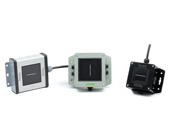
Irradiance Sensors (Reference Cells) are measurement devices used to measure the solar irradiance incident on the module plane in power plants in units of W/m² (Plane of Array – POA). The sensor has a spectral and angular response similar to PV modules, represents the actual operating conditions of the module, and shall be used as the primary reference data source for Performance Ratio (PR) calculations.
3.1. Number of Sensors to be Used
The number of sensors to be used in the plant is defined in the IEC 61724-1:2021 standard and is provided in the table below. In sites below 40 MW, 2 (two) sensors are recommended. This condition is also valid for small-scale sites. For example, in a 1 MW site, 2 irradiance sensors shall also be used. The reason for this is that one of the sensors serves as a backup. In this way, by comparing the measurement results of the sensors, accurate measurement verification can be achieved, and in case of failure of one sensor or if it is sent for calibration, using two irradiance sensors ensures data reliability and continuity.
However, if there are different orientations (azimuth or tilt angle) in the site, one irradiance sensor shall be used for each azimuth and each tilt angle. Otherwise, PR shall not be calculated correctly. If a single sensor is used despite having different azimuth and tilt angles, the performance ratio will be either higher or lower than it should be depending on the installation angle of the sensor, and this value will fluctuate during the day. However, in some sloped terrains, using one sensor for each angle may be costly and may not be feasible. In this case, the optimum number that will represent the site shall be determined by the investor.
| Installed Capacity (AC) MW | Number of Irradiance Sensors |
| < 40 | 2 |
| ≤ 40 to 100 | 3 |
| ≤ 100 to < 300 | 4 |
| ≤ 300 to < 500 | 5 |
| ≤ 500 to < 700 | 6 |
| ≤ 700 | 7, plus 1 for each additional 200 MW |
Table 3: Minimum Irradiance Sensor Quantity Requirements According to IEC 61724-1:2021
3.2. Technical Specifications
The technical requirements specified in this draft specification are determined based on international standards; equivalent products that meet these requirements may be offered.
- Uncertainty: ≤1% (IEC 61724-1:2021 standard, Class A)
- Resolution: ≤1 W/m² (IEC 61724-1:2021 standard, Class A)
- Measurement Range: 0–1600 W/m² or higher
- Response Time: 1 s
- Field of View: >160° and there shall be no step difference between the cell glass and the sensor surface; they shall be at the same level. In case of a step difference, water and dust accumulation may occur at these points, which may negatively affect sensor accuracy over time.
- Communication Protocol: Modbus RTU or SunSpec shall be used over RS-
- Cable Length: It shall be directly connected to the data logger or SCADA For this, it shall be of sufficient length without requiring additional joints in the field.
- Cable Specifications: LIYYC11Y PUR Cable, 6-core, twisted pairs, depending on length 24 AWG or 26 AWG, UV resistant, RS-485 communication cable.
- Protection Class: Minimum IP54 or higher
- Warranty Period: Minimum 2 years
- Material: UV resistant, corrosion-protected material
- Supply Voltage: 12–30 V DC (Recommended 24 V DC)
- Daisy Chain: It shall be suitable for communication over a single Modbus If needed, a daisy chain connection port shall be available on the sensor by the manufacturer. Thus, multiple sensors can be connected to each other, providing savings in cabling.
- External Sensor Connection: It shall be suitable for connection of project-required auxiliary sensors (Module Temperature Sensor, Wind Speed Sensor, Wind Direction Sensor, Relative Humidity and Ambient Temperature Sensor).
- Compliant Standards: Irradiance sensor technical specifications shall be fully compliant with IEC 61724-1:2021 standard.
- Calibration: It shall be performed in accordance with IEC 60904-2 standard
Since contamination directly affects measurement accuracy, irradiance sensors with automatic cleaning features shall be used in regions where contamination is intense. Similarly, in regions where frost and snowfall are frequent, irradiance sensors with a heating feature shall be used.
3.3. Calibration and Certification
The irradiance sensor is the most critical sensor for PV plants, as the Performance Ratio of the plant is calculated based on the data from this sensor. In sensor technologies, the most critical issue is calibration. Calibration not performed in accordance with standards and by an accredited laboratory may cause problems for such a critical sensor. For this reason, the following conditions shall be ensured in irradiance sensor calibration.
- ISO 17025 accredited laboratory calibration shall be performed with a calibrated reference cell, and the calibration certificate prepared in accordance with IEC 60904-2 standard shall be delivered with the The laboratory issuing the certificate shall be accredited according to ISO 17025 standard. The validity and authenticity of the provided certificates shall be verifiable via online platforms.
- In the calibration certificates, the sensor serial number, calibration date, and measurement uncertainty (k = 2) shall be clearly specified. The certificate shall comply with ISO 17025 standard requirements.
- If irradiance sensor calibration is to be performed in the manufacturer’s laboratory, an accreditation document showing that this laboratory complies with ISO 17025 standard shall be submitted to the Investor’s Representative during the product approval process. Calibration performed in laboratories not accredited according to this standard shall not be accepted. In this case, a document committing that calibration will be performed by a third-party accredited laboratory shall be submitted.
- Sensors shall be recalibrated every two years. Calibration certificates of the sensors shall be recorded, and recalibration periods shall be monitored by the plant operator.
- New calibration values shall be integrable into the sensor via its software. Products in which the calibration value can only be entered by the manufacturer shall not be approved by the Investor’s Representative. The manufacturer’s commitment on this matter shall be submitted to the Investor’s Representative during the product approval process.
3.4. Installation and Mounting Conditions
- Sensors shall be installed at the same tilt and azimuth angle as the
- They shall be placed in an open area where they will not be affected by shading, reflection, or local
- A homogeneous distribution shall be ensured in a way that represents the
- The mounting surface shall be stable and free of
- The installation rules in Section 7 and the grounding rules in Section 2.8 shall be applied.
4. PYRANOMETER
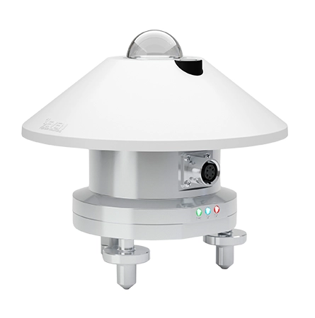
Pyranometers are used to measure GHI (Global Horizontal Irradiance) or POA (Plane of Array) irradiance reaching the earth’s surface from the sun. These measured data can be used for photovoltaic system performance analysis, feasibility assessments based on meteorological data, and long-term climatic monitoring studies. It is recommended that one pyranometer be installed for GHI measurement in each plant. During the plant design phase, the number and type of sensors to be used shall be selected according to Section 2.1. Types, Classes, and Quantities of Sensors to be Used in the Field.
The technical requirements specified for the Pyranometer in this draft specification are determined based on international standards and allow the offering of equivalent products that meet these requirements.
4.1. Standards and References
The pyranometer to be offered shall comply with the following standards:
- ISO 9060:2018 – Pyranometer classification and performance criteria
- IEC 61724-1:2021 – Photovoltaic system performance monitoring and irradiance measurement requirements
Pyranometer Accuracy Class Selection Criteria
The accuracy class of the pyranometers to be installed shall be determined in line with the performance monitoring requirements of the plant, and the measurements shall comply with the performance monitoring and data quality requirements defined in the IEC 61724-1 standard. Only Class A pyranometers shall be used in plants. The use of lower class pyranometers is not economically justified. This is because a Class A PV Reference Cell type Irradiance Sensor is both more economical and has better accuracy compared to Class B or Class C pyranometers.
4.2. Technical Specifications
- Sensor Type: Thermopile-based Pyranometer
- Measured Value: Global Horizontal Irradiance (GHI) or Plane of Array Irradiance (POA)
- Measurement Range: Minimum 0–1600 W/m² or higher
- Compliant Standards: Technical specifications shall be fully compliant with ISO 9060:2018 Class A and IEC 61724-1:2021 Class A standards
- Uncertainty: ≤2%
- Spectral range: Approximately 285–2800 nm or wider
- Irradiance Resolution: ≤ 1 W/m²
- Response Time (95%): ≤ 1 second or less
- Communication Protocol: Modbus RTU or SunSpec shall be used over RS-485
- Cable Length: It shall be directly connected to the data logger or SCADA For this, it shall be of sufficient length without requiring additional joints in the field
- Cable Specifications: LI2(ST)C11Y-PUR Cable, 6-core, twisted pairs, depending on length 24 AWG or 26 AWG, UV resistant, RS-485 communication cable
- Protection Class: Minimum IP65 or higher
- Warranty Period: Minimum 5 years
- Material: UV resistant, corrosion-protected material
- Supply Voltage: 12–30 V DC (Recommended 24 V DC)
- Operating Temperature: −40 °C to +80 °C or wider
- Calibration: It shall be performed in accordance with ISO 9847 standard requirements
4.3. Calibration and Certification
Irradiance sensors are the most critical sensors for PV plants, as the Performance Ratio of the plant is calculated based on the data from these sensors. In sensor technologies, the most critical issue is calibration. Calibration not performed in accordance with standards and by an accredited laboratory may cause problems for such critical sensors. For this reason, the following conditions shall be ensured in irradiance sensor calibration.
- Calibration shall be performed in accordance with ISO 9847 standard using a comparative method with traceable reference pyranometers.
- The laboratory issuing the certificate shall be accredited according to ISO 17025 standard. The validity and authenticity of the provided certificates shall be verifiable via online platforms.
- In the calibration certificates, the sensor serial number, calibration date, and measurement uncertainty (k = 2) shall be clearly The certificate shall comply with ISO 17025 standard requirements.
- If pyranometer calibration is to be performed in the manufacturer’s laboratory, an accreditation document demonstrating that this laboratory complies with ISO 17025 standard shall be submitted to the Investor’s Representative during the product approval process. It is sufficient that the scope of accreditation includes calibration of any type of irradiance sensor. Calibration performed in laboratories not accredited according to this standard shall not be In this case, a document committing that calibration will be performed by a third-party accredited laboratory shall be submitted.
- Sensors shall be recalibrated every two years. Calibration certificates of the sensors shall be recorded, and recalibration periods shall be monitored by the plant operator.
- New calibration values shall be integrable into the sensor via its software. Products in which the calibration value can only be entered by the manufacturer shall not be approved by the Investor’s Representative. The manufacturer’s commitment on this matter shall be submitted to the Investor’s Representative during the product approval process.
4.4. Installation and Mounting Conditions
- The pyranometer that will provide GHI (Global Horizontal Irradiance) measurement shall be installed completely parallel to the horizontal The exact horizontal position shall be ensured by checking with the spirit level on the device.
- The pyranometer that will provide POA (Plane of Array) measurement shall be installed at the same tilt angle and in the same azimuth direction as the photovoltaic panels.
- The sensor shall be placed in an open area where it will not be affected by shading, reflection, or local obstructions.
- A homogeneous distribution shall be ensured in a way that represents the
- The mounting surface shall be stable and free of
- The installation rules in Section 7 and the grounding rules in Section 2.8 shall be applied.
5. ALBEDOMETER
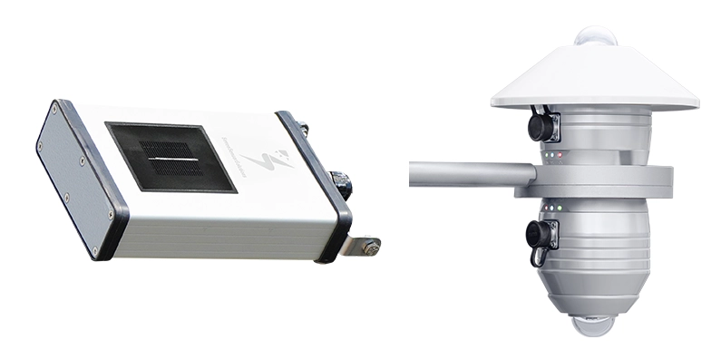
Albedometers are measurement devices used in photovoltaic (PV) plants to measure the front-side irradiance incident on the panel plane and the rear-side irradiance reflected from the ground, in order to enable accurate calculation of the Performance Ratio (PR) of bifacial panels. The measured data are used to calculate the albedo ratio, and the bifacial energy yield contribution is determined accurately. Therefore, in plants using bifacial panels, the use of a PV Albedometer is mandatory.
Albedo measurement can be performed using a Thermopile Pyranometer or an Irradiance Sensor/Reference Cell. In both cases, the sensors shall be installed at the panel angles. POA irradiance shall be measured from both the front side and the rear side. Since standards define albedometers mostly for meteorological purposes, they describe horizontal installation. However, the albedo value calculated based on GHI measurement will not provide a reliable performance evaluation. Therefore, measurements shall be performed in the panel plane. However, for comparison with meteorological data, for comparison with previously collected historical data from the site, or for general evaluation in uneven terrains, pyranometers may be installed horizontally and used in albedo calculation.
In POA albedometer applications, since both the irradiance incident on the front surface and the irradiance incident on the rear surface of the panel are measured, there is no need to use an additional irradiance sensor for the front surface. PR calculation can be performed based on the irradiance values from these two surfaces. The selected product shall transmit front-side irradiance data, rear-side irradiance data, albedo ratio, and panel temperature data separately in registers and under a single ID.
5.1. Technical Specifications
The technical requirements specified in this draft specification are determined based on international standards and allow the offering of equivalent products that meet these conditions. The following requirements shall be met for the sensors located on both surfaces to be used in the albedometer:
- Measurement Output: Front-side irradiance data, rear-side irradiance data, albedo ratio, and panel temperature data shall be provided over a single ID. (When a pyranometer is used, there is no requirement for albedo ratio or panel temperature data)
- Uncertainty: ≤2% (IEC 61724-1:2021 standard, Class A)
- Resolution: ≤1 W/m² (IEC 61724-1:2021 standard, Class A)
- Measurement Range: 0–1500 W/m² or higher
- Response Time: 1 s
- Field of View: >160°
- Communication Protocol: Modbus RTU or SunSpec shall be used over RS-485
- Cable Length: It shall be directly connected to the data logger or SCADA For this, it shall be of sufficient length without requiring additional joints in the field
- Cable Specifications: LIYYC11Y PUR Cable, 6-core, twisted pairs, depending on length 24 AWG or 26 AWG, UV resistant, RS-485 communication cable
- Protection Class: Minimum IP54 or higher
- Warranty Period: Minimum 2 years
- Material: UV resistant, corrosion-protected material
- Supply Voltage: 12–30 V DC (Recommended 24 V DC)
- Daisy Chain: It shall be suitable for communication over a single Modbus If needed, a daisy chain connection port shall be available on the sensor by the manufacturer. Thus, multiple sensors can be connected to each other, providing savings in cabling. When a Pyranometer is used, this condition is not required
- External Sensor Connection: A Module Temperature Sensor shall be This condition is not required when a Pyranometer is used
- Calibration: Calibration shall be performed in accordance with IEC 60904-2 standard, by following Section 3 of this document. For albedometers using pyranometers, calibration shall be performed in accordance with ISO 9847 standard, by following Section 4.3 of this document.
5.2. Installation and Mounting Conditions
- Sensors shall be installed at the same tilt and azimuth angle as the panels. The height shall be the same as the mounting height of the panels from the ground. In applications where albedo is calculated based on GHI with horizontal installation, the height of the albedometer from the ground shall be at least 1 meter.
- They shall be placed in an open area where they will not be affected by shading, reflection, or local
- The rear-side sensor position shall be selected to provide a field of view that represents the majority of the PV array. This field of view shall not be less than ±80 degrees.
- If the ground surface or albedo characteristics vary, a sufficient number of sensors shall be used and an appropriate sampling methodology shall be applied.
- The mounting surface shall be stable and free of
- The installation rules in Section 7 and the grounding rules in Section 2.8 shall be applied.
6. SOILING SENSOR
6.1. Automatic and Manual Soiling Sensors
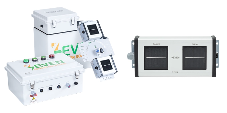
Soiling forms a layer on the panel surface, preventing solar irradiance from reaching the photovoltaic cells and reducing energy production. For this reason, at least one soiling sensor shall be installed in plants. If there is more than one panel angle in the plant, one soiling sensor shall be installed for each angle.
Based on the data obtained from the sensor, the energy loss caused by soiling is calculated as follows. If the resulting amount is greater than the cost required to clean the plant, the plant shall be cleaned.
- Soiling sensor reading = 5%
- Monthly revenue of the plant = $A
- Cleaning cost of the plant = $B
If B ≤ A × 0.05, the plant shall be cleaned.
Since this calculation cannot be performed without a soiling sensor, a soiling sensor shall be installed in the plant. In sites with a capacity above 1 MW, the presence of a soiling sensor is mandatory. Otherwise, energy losses caused by soiling in the plant cannot be observed.
6.1.1. Standards and Compliance
The soiling monitoring station shall comply with the requirements of IEC 61724-1:2021 (Annex C) and shall implement Method No. 2, which is based on the measurement of the reduction in short-circuit current due to soiling. According to this standard, the sensor shall collect data only within the time window starting two hours before and ending two hours after local solar noon (i.e., when the sun is at its highest position). The sensor shall be capable of determining the local solar time of the plant. For this purpose, the plant coordinates shall be configurable via the sensor interface, and the sensor shall process only the data collected within this four-hour period. Data collected outside this period shall increase the measurement uncertainty of the sensor.
The sensor shall have software that performs stable data separation. Fluctuations in solar irradiance significantly affect sensor uncertainty. Therefore, the sensor shall filter the values specified in the relevant standard and shall provide the number of stable data points obtained via a separate register in its interface.
The sensor shall display both the instantaneous soiling ratio and the daily average soiling ratio. However, the value to be considered, according to the above standard, is the Daily Average Soiling Ratio. The soiling ratio is not expected to change during the day. Therefore, after the calculation is completed, it is appropriate to calculate a single daily average value and perform the evaluation based on this ratio.
6.1.2. Technical Specifications
The system shall determine the soiling ratio using two reference devices installed at the same tilt angle as the PV modules and in the panel plane (Plane of Array – POA), thereby ensuring that the measurements are representative and comparable.
One reference cell shall be kept clean, while the other reference cell shall be exposed to natural soiling conditions (same as the panels).
- Sensor Type: It shall be based on a reference cell and have a comparative measurement system with two sensors, one clean and the other soiled.
- Coordinate Information: The sensor interface shall allow entry of the plant location
- Measurement Range: It shall be capable of measuring Soiling Ratio in the range of 0% to 100%.
- Measurement Accuracy: It shall have an uncertainty of ≤ 1%.
- Resolution: It shall be 1% or better.
- Measured Parameters: Daily Average Soiling Ratio, Instantaneous Soiling Ratio, Water Tank Status Information, Soiled/Clean Cell Irradiance and Cell Temperature Values, Number of Stable Data Points
- Power Supply: 110–240 V AC or 24 V 5 A DC
- Protection Class: Minimum IP54 or higher
- Warranty Period: Minimum 2 years
- Data Output: The sensor shall support Modbus RTU communication protocol via RS-485
- The clean reference cell shall be cleaned daily either automatically or manually. The user shall be able to configure the number of daily cleaning cycles, and the system shall support a maximum of three (3) cleaning cycles per day.
- In manual soiling sensors, the clean reference cell shall be cleaned regularly by site personnel at intervals appropriate to the defined soiling monitoring periods, in a way that maintains measurement accuracy.
- Soiling sensors with automatic normalization feature shall be
- The soiled reference device shall be cleaned together with the panels during PV module cleaning operations carried out at the plant.
- For Automatic Soiling Sensors, the system shall be provided with an integrated water tank suitable for the cleaning mechanism.
- The user shall be able to define the automatic cleaning time, and cleaning shall not be performed around local solar noon to minimize measurement uncertainty and improve accuracy.
- The system shall provide a resolution of minimum 1% and an uncertainty of ≤ 1%, and irradiance sensors compliant with IEC 61724-1 Class A standards shall be preferred.
- The soiling sensor shall support Modbus RTU communication and shall be fully compatible with the Modbus-supported data logger available at the plant.
- All required mounting structures, accessories, and installation equipment shall be provided by the manufacturer and shall be fully compatible with open-field PV plant conditions.
6.1.3. Calibration and Certification
The soiling sensor consists of two irradiance sensors, and the initial calibration shall be performed in accordance with IEC 60904-2 by following Section 3.3 of this document. Subsequent calibrations shall be able to be performed in the field using the automatic normalization feature.
6.2. Portable Soiling Sensor
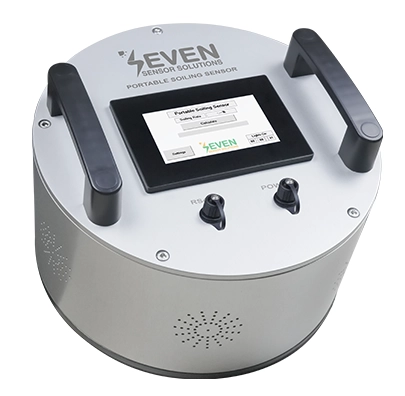
Portable soiling sensors are used by operation and maintenance (O&M) teams, cleaning contractors, and EPC companies to evaluate the soiling ratio across multiple photovoltaic (PV) plant sites or to determine the contamination levels at different locations within a single site. It is especially recommended if different soiling behaviours exist at different points of a plant. For example, if certain parts of the plant experience more soiling than others, multiple fixed soiling sensors shall be used. However, a portable soiling sensor can provide a more economical solution to this need. With a single portable soiling sensor available at the plant, multiple measurements can be taken at different locations and used for evaluation.
The device shall be designed to be handheld and easily deployable across different PV arrays and areas without requiring a fixed installation.
The Portable Soiling Sensor shall operate based on an optical measurement principle and determine the soiling ratio by measuring changes in irradiance or photocurrent caused by soiling accumulation. The sensor may not display values below 2%, as values below 2% remain below the cleaning cost threshold.
6.2.1. Technical Specifications
- Measurement Time: Maximum 10 minutes
- Measurement Range: 2% – 20%
- Output: Via HMI display
- Sensor Accuracy: ±2% or better
- Battery: Rechargeable lithium battery
7. MODULE TEMPERATURE SENSOR

Module Temperature Sensors (also referred to as panel back-side temperature sensors) are sensors used to measure the rear surface temperature of panels in photovoltaic (PV) power plants. The measured panel temperature data shall be used to determine power variation using the temperature coefficient of PV modules and in Performance Ratio (PR) calculations corrected for temperature effects.
In the IEC 61724-1 standard, it is stated that 6 temperature sensors shall be used for sites smaller than 40 MW. However, the standard does not specify a separate number for very low-capacity installations. Due to its impact on Performance Ratio calculation, regardless of how small the site is, at least the same number of module temperature sensors as irradiance sensors shall be used. For large-capacity sites, three additional module temperature sensors shall be installed for every 200 MW above 100 MW.
During the plant design phase, the number and type of sensors to be used shall be selected in accordance with Section 2.1 Types, Classes, and Quantities of Sensors to be Used in the Field in order to ensure high-accuracy Performance Ratio calculation.
7.1. Standards and Compliance
- The sensor shall have Class A measurement accuracy in accordance with IEC 60751:2022
- The sensor and measurement method shall comply with the photovoltaic plant monitoring requirements defined within the scope of IEC 61724-1:2021 Annex The sensor size shall not be greater than 10% of the panel cell size. The sensor shall not be enclosed in an aluminium housing. The sensor shape shall be circular as shown in the standard.
7.2. Technical Specifications
- The module temperature sensor shall meet the Class A monitoring requirements defined in IEC 61724-1:2017 and shall have the structural characteristics specified in Annex The sensor element shall be a PT1000-type platinum resistance thermometer (RTD) with Class A tolerance in accordance with IEC 60751. The sensor shall be circular as shown in the standard, and the covered area shall not exceed 10% of a single cell area.
- Measurement Range: Minimum -40 °C to +85 °C
- Measurement Accuracy: ±1 °C
- Resolution: 1 °C
- Supply Voltage: It shall be in the range of 12–30 V DC
- Protection Class: Sensor minimum IP67, signal converter enclosure minimum IP65
- Warranty Period: Minimum 2 years
- Data Output: The sensor shall support at least one of the following output options depending on application requirements
- PT1000 output (recommended). It shall be directly connected to the irradiance sensor or compact weather station
- Analog 4–20 mA output
- Analog 0–10 V output
- Modbus RTU communication protocol via RS-485 interface
- Measurement Signals: It shall be directly connectable to data loggers or monitoring systems
7.3. Installation and Mounting Conditions
- The sensor shall be designed to be in direct contact with the rear surface of the PV
- Aluminium material shall not be preferred for temperature sensors to be used on the rear surface of the Since aluminium and similar metals do not exhibit the same thermal behaviour as panel rear surfaces according to IEC 61724-1 standard, their response to temperature changes differs. The sensor body and contact surfaces shall be made of materials that do not create chemical or electrical reactions with the module and provide long-term environmental durability, and shall have one of the following structures:
- Laminatable structure between EVA and Tedlar layers
- UV-resistant ABS plastic injection housing
- The sensor dimensions shall be compact and smaller than 10% of the area of a single cell on the
- The sensor shall be mountable to the rear surface of the panel using 3M tape with high thermal conductivity, resistant to UV and environmental conditions.
- The cable structure shall be made of PUR or equivalent material resistant to UV and environmental
- Auxiliary equipment such as adhesive bases, clips, and double-sided 3M tape shall be provided for cable mounting support.
- The cable length shall be determined to be sufficient for PV plant applications according to the sensor output signal; for example, a maximum of 20 m shall be used for PT1000 and 4–20 mA analog outputs, and up to 800 m shall be used for RS-485 outputs.
8. AMBIENT TEMPERATURE SENSOR
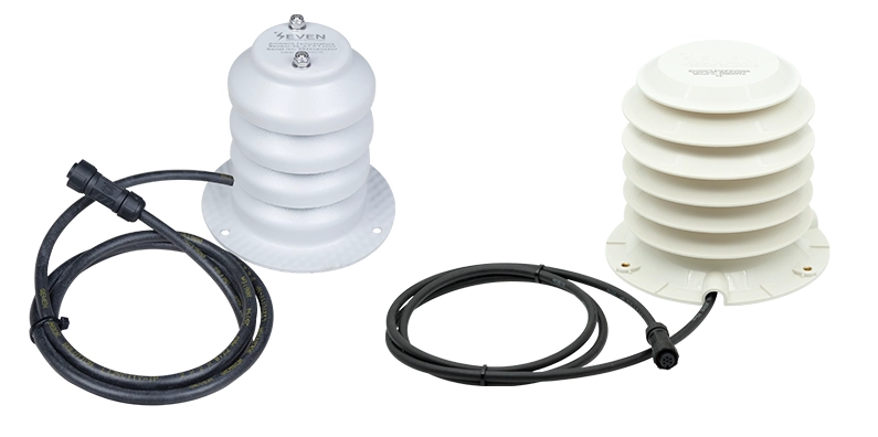
Ambient Temperature Sensors are measurement devices used to measure the ambient air temperature in photovoltaic (PV) power plants.
It is recommended to have one ambient temperature sensor in each plant for ambient temperature measurement. During the plant design phase, the number and type of sensors to be used shall be selected in accordance with Section 2.1 Types, Classes, and Quantities of Sensors to be Used in the Field.
8.1. Standards and Compliance
- The sensor shall have a PT1000 sensing element with Class A accuracy in accordance with IEC 60751:2022 standard.
- The sensor and measurement method shall comply with the photovoltaic plant monitoring requirements defined within the scope of IEC 61724-1:2021 Annex B.
8.2. Technical Specifications
- Sensor Type: PT1000 RTD (Resistance Temperature Detector)
- Radiation Shield: The ambient temperature sensor shall be equipped with a radiation shield that protects it from direct solar radiation while allowing air flow, made of UV-resistant ABS material, with metal mounting points embedded in the plastic structure, and supplied with the product; it shall consist of at least 7 plates.
- Measurement Range: Minimum −40 °C to +85 °C
- Measurement Accuracy: ±0.1 °C or better
- Resolution: 1 °C or better
- Supply Voltage: It shall be in the range of 12–30 V DC
- Protection Class: Sensor minimum IP67; if applicable, signal converter enclosure minimum IP65
- Warranty Period: Minimum 2 years
- Data Output: The sensor shall support at least one of the following output options depending on application requirements
- PT1000 output (recommended). It shall be directly connected to the irradiance sensor or compact weather station
- Modbus RTU communication protocol via RS-485 interface
- Analog 4–20 mA signal output
- Analog 0–10 V signal output
8.3. Installation and Mounting Conditions
- The sensor shall be provided with a UV-resistant ABS radiation shield designed to prevent direct solar radiation exposure and to allow free air circulation with the ambient The mounting points of the radiation shield shall consist of metal inserts embedded in the plastic body; direct fastening into plastic shall not be permitted as it may lead to cracking and material degradation over time.
- The sensor enclosure shall have a minimum IP67 protection class and shall be resistant to UV radiation, rain, dust, and harsh outdoor environmental conditions.
- The sensor shall be mountable on a pole, ground, or suitable supporting structure in a way that does not obstruct air flow in open areas.
- The cable structure shall be made of PUR or equivalent material resistant to UV and environmental
- The cable length shall be selected in accordance with the sensor output signal and shall be sufficient for PV plant applications. In order to maintain signal integrity, measurement accuracy, and communication reliability, the cable length shall not exceed 20 meters for PT1000 and 4–20 mA analog output sensors, and 800 meters for sensors using RS-485 communication.
9. RELATIVE HUMIDITY SENSOR
Relative Humidity Sensors are measurement devices used to measure the ambient relative humidity in photovoltaic (PV) power plants. Depending on the humidity level, dew formation may occur on the panels, which may lead to performance losses. A humidity sensor is required to detect such conditions.
It is recommended to have 1 relative humidity sensor in each plant. During the plant design phase, the number and type of sensors to be used shall be selected in accordance with Section 2.1 Types, Classes, and Quantities of Sensors to be Used in the Field.
9.1. Standards and Compliance
- Relative humidity measurement shall meet Class A requirements in accordance with IEC 61724-1:2021 standard.
- Optionally, the relative humidity sensor may be provided as an integrated unit with the ambient temperature sensor, in accordance with the relevant specification requirements.
9.2. Technical Specifications
- Sensor Type: It shall be a capacitive type relative humidity sensor. It may have an integrated structure and may also provide temperature and pressure data.
- Radiation Shield: The humidity sensor shall be equipped with a radiation shield that protects it from direct solar radiation while allowing air flow, made of UV-resistant ABS material, with metal mounting points embedded in the plastic structure, and supplied with the product.
- Measurement Range: 0% – 100% RH
- Measurement Accuracy: ±1% or better within the range of 20% … 70% RH
- Resolution: 1% RH or better
- Supply Voltage: It shall be in the range of 12–30 V DC
- Protection Class: Sensor minimum IP67; if applicable, signal converter enclosure minimum IP65
- Warranty Period: Minimum 2 years
- Data Output: The sensor shall support at least one of the following output options depending on application requirements
- Digital I²C interface (recommended). It shall be directly connected to the irradiance sensor or compact weather station
- Analog 4–20 mA output (relative humidity)
- Modbus RTU communication protocol via RS-485 interface
9.3. Installation and Mounting Conditions
- The sensor shall be provided with a UV-resistant ABS radiation shield designed to prevent direct solar radiation exposure and to allow free air circulation with the ambient The mounting points of the radiation shield shall consist of metal inserts embedded in the plastic body; direct fastening into plastic shall not be permitted as it may lead to cracking and material degradation over time.
- The sensor enclosure shall have a minimum IP67 protection class and shall be resistant to UV radiation, rain, dust, and harsh outdoor environmental conditions.
- The sensor shall be mountable on a pole, ground, or suitable supporting structure in a way that does not obstruct air flow in open areas.
- The cable structure shall be made of PUR or equivalent material resistant to UV and environmental
- The cable length shall be selected to be at least 5 meters and sufficient for PV plant applications. It may be shorter in compact weather stations.
10. WIND SPEED SENSOR
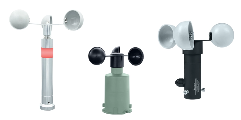
Wind Speed Sensors are devices used in photovoltaic (PV) power plants to measure wind speed for environmental monitoring, performance analysis, and provision of meteorological data in accordance with IEC 61724-1.
Wind speed measurement is required to determine the convective cooling effect that influences the surface temperature of PV modules. Since module temperature directly affects energy production efficiency, wind speed data shall be used as a supporting parameter in Performance Ratio (PR) calculations, temperature correction analyses, and particularly in module temperature modelling and environmental impact assessments.
In addition, wind speed sensors shall be used for verifying wind-induced structural or equipment failures and for supporting insurance processes related to such failures with technical data, and their provision is essential within the scope of the project.
10.1. Standards and Compliance
- The sensor shall comply with the photovoltaic plant monitoring and meteorological measurement requirements defined within the scope of IEC 61724-1:2021
10.2. Technical Specifications
- Sensor Type: It shall be an anemometer capable of measuring horizontal wind speed and operating independently of wind direction.
- Operating Principle: It shall operate based on the cup type anemometer
- Measurement Range: Minimum 9 m/s – 60 m/s
- Resolution: Minimum 1 m/s
- Measurement Accuracy:
- For speeds below 5 m/s: ±0.5 m/s
- For speeds above 5 m/s: ±10% of the measured value or better
- Survival Wind Speed: It shall withstand a minimum survival wind speed of 60 m/s
- Operating Temperature Range: −40 °C to +85 °C (under non-icing conditions)
- Supply Voltage: It shall be in the range of 12–30 V DC
- Warranty Period: Minimum 2 years
- Data Output: The sensor shall support at least one of the following output options depending on application requirements
- Pulse output. (It shall be directly connected to the irradiance sensor or compact weather station)
- Analog 4–20 mA output
- Modbus RTU communication protocol via RS-485 interface
- Communication and output signals shall be designed to ensure reliable operation under industrial electromagnetic noise and harsh site conditions.
10.3. Installation and Mounting Conditions
- The sensor shall be suitable for long-term use in open field and PV plant environments and shall have a structure resistant to environmental conditions.
- The sensor body and mechanical components shall be resistant to UV radiation, rain, wind, and temperature The body shall be made of anodized aluminium, or if it has an ASA plastic cup, it shall be made of ABS plastic material.
- The sensor shall have a mechanical structure suitable for mounting on a pole or ground. The connection points shall consist of metal inserts embedded in the plastic body; direct fastening into plastic shall not be permitted as it may lead to cracking and material degradation over time.
- After installation, the sensor shall be installed in a manner that prevents exposure to vibration or mechanical stress that may affect measurement accuracy.
- The cup structure shall have an aerodynamic design that allows accurate detection of wind
- The sensor cable shall be of industrial-grade structure resistant to UV and environmental
- The cable length shall be not less than 1.5 meters and shall be suitable for installation in PV plant applications; shorter cable lengths may be accepted for compact weather station configurations.
11. WIND DIRECTION SENSOR
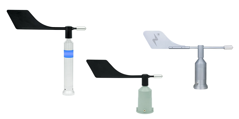
Wind Direction Sensors are devices used in photovoltaic (PV) power plants to monitor environmental conditions, analyse wind characteristics, and provide meteorological data within the scope of IEC 61724-1 standard, by measuring the wind direction parameter.
Wind direction data is used to determine whether the incoming wind is from the north or the south, and accordingly to understand whether it will cause a heating effect or a cooling effect on the panel.
Products that do not meet the specified measurement accuracy, environmental durability, and standard compliance shall not be considered equivalent.
11.1. Standards and Compliance
- The sensor shall comply with the photovoltaic plant monitoring and meteorological measurement requirements defined within the scope of IEC 61724-1:2021 standard.
- The sensor shall be capable of enabling the evaluation of the effects of wind direction on panel configurations and environmental conditions.
11.2. Technical Specifications
- Measurement Range: Wind direction shall be continuously and uninterruptedly measurable in the range of 0–359°.
- Sensor Type: It shall be of vane-type design and shall perform measurement based on the Hall-effect position sensing principle.
- Resolution: Minimum 1°
- Measurement Accuracy: ±1% of the measured value or better
- The sensor shall be capable of detecting direction at low wind speeds, and the starting threshold shall be a maximum of 1 m/s.
- Operating Temperature Range: −40 °C to +85 °C (under non-icing conditions)
- Supply Voltage: It shall be in the range of 12–30 V DC
- Protection Class: Minimum IP54 for the sensor and, if applicable, the signal converter enclosure
- Warranty Period: Minimum 2 years
- Data Output: The sensor shall support at least one of the following output options depending on application requirements
- Analog 0–3.3 V output (recommended). It shall be directly connected to the irradiance sensor or compact weather station
- Analog 4–20 mA output
- Modbus RTU communication protocol via RS-485 interface
- Communication and output signals shall be designed to ensure reliable operation under industrial electromagnetic noise and harsh site conditions.
11.3. Installation and Mounting Conditions
- The sensor shall be suitable for long-term use in open field and PV plant environments and shall have a structure resistant to environmental conditions.
- The sensor body and vane structure shall be made of aluminium or ASA plastic, resistant to UV radiation, rain, wind, and temperature variations.
- The sensor shall have a mechanical structure suitable for mounting on a pole or ground. The connection points shall be metal inserts embedded into the plastic body. Otherwise, direct tightening of screws into the plastic body may cause cracks and breakage in the material over
- After installation, the sensor shall not be exposed to mechanical stress, looseness, or vibration that may affect measurement accuracy.
- The vane structure shall have an aerodynamic design that ensures accurate and stable wind direction
- The sensor cable shall be of industrial-grade structure resistant to UV and environmental
- The cable length shall be at least 2 meters and shall be selected to be suitable for installation in PV plant applications; it may be shorter in compact weather stations.
12. RAIN GAUGE
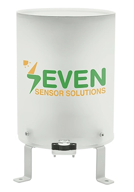
Rain Gauges are used in meteorological measurement and PV performance monitoring applications to detect precipitation. Precipitation data is a required parameter for accurate evaluation of irradiance measurements, energy production analyses, and maintenance/cleaning planning.
12.1. Standards and Compliance
- The sensor shall be compatible with the monitoring systems used within the scope of IEC 61724-
12.2. Technical Specifications
- Measured Parameter: Precipitation amount
- Sensing Type: Tipping bucket
- Measurement Units: mm/s, mm/min, or mm/h
- Measurement Range: 0–500 mm/h
- Resolution: 2 mm or better
- Accuracy:
- ±1% (0–30 mm/h)
- ±2% (30–100 mm/h)
- ±5% (100–600 mm/h)
- Operating Temperature: 0 °C to +80 °C or wider
- Sensor Body: UV-resistant, corrosion-protected material
- Mounting: Mounting accessories shall be provided with the sensor
- Protection Class: Minimum IP65 or higher
- Warranty Period: Minimum 2 years
- Data Output: The sensor shall support at least one of the following output options depending on application requirements
- RS-485 (Modbus RTU)
- Pulse output (reed relay) (It can be connected to a compact weather station)
These sensors operate based on the tipping bucket principle and transmit data via RS-485 using Modbus RTU or via pulse output (reed relay).
12.3. Calibration and Certification
- The device shall be factory-
- The calibration report/certificate shall be
- The user and installation manual shall be
- The sensor serial number shall be clearly stated in the
12.4. Installation and Mounting Conditions
As the installation of the rain sensor directly affects measurement accuracy, it shall be carried out in accordance with the following rules:
- The sensor shall include a spirit level or shall be mounted in a perfectly horizontal position using an external spirit level.
- The sensor shall be positioned so that its upper part has an unobstructed view of the open sky, ensuring that precipitation reaches the bucket without obstruction.
- The sensor shall be installed at a location that allows easy access to the bucket for maintenance and cleaning purposes.
- The sensor shall be positioned so as not to be exposed to rainfall obstruction caused by building eaves, panels, poles, or other structures.
- The mounting height shall be selected to reduce splash effects and minimize environmental
12.5. Maintenance and Periodic Inspection Requirements
To maintain measurement accuracy of the rain gauge, maintenance and inspection activities shall be performed regularly. In this context, maintenance requirements shall be in compliance with the IEC 61724-1 maintenance approach accepted for meteorological measurement equipment.
Routine Inspections
- The monitoring system and sensors shall be inspected at least once a year and preferably at more frequent intervals in accordance with Section 5.6 Inspection of IEC 61724-1:2021 standard.
- It shall be checked whether there is any loosening, deformation, or mechanical damage in the mounting components.
- It shall be checked at regular intervals whether there are any accumulations such as leaves, dust, insects, etc. in the sensor bucket.
- It shall be verified that the water drainage holes are not
- The horizontal position of the sensor (level alignment) shall be
13. SNOW SENSOR
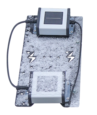
Snow Sensors are measurement devices used to determine production losses caused by snow accumulation on photovoltaic (PV) modules. Snow sensors can be used for the following purposes:
- Determination of production losses caused by snow
- Analysis of the causes of performance degradation
- Monitoring of plant performance under winter conditions
- For tracker systems to eliminate snow load
Snow measurements shall be based on the comparative irradiance measurement principle. Within this scope, two reference cells are used.
- One reference cell remains under the same environmental and operating conditions as the PV modules
- The other reference cell is heated and kept free of snow
By comparing the irradiance values obtained from the two reference cells, the energy loss ratio caused by the snow cover on the PV modules is measured.
If the snow ratio is 10%, this means that there is a 10% energy loss at the plant due to snow.
13.1. Technical Specifications
- Uncertainty: ≤2% (Class A according to IEC 61724-1:2021 standard)
- Resolution: ≤1 W/m² (Class A according to IEC 61724-1:2021 standard)
- Measurement Range: 0–1500 W/m²
- Cell Field of View: >160°
- Snow Ratio: 0% – 100%
- Communication Protocol: Modbus RTU or SunSpec shall be used over RS-485
- Cable Length: It shall be directly connected to the data logger or SCADA For this, it shall be of sufficient length without requiring additional joints in the field
- Cable Specifications: LIYYC11Y PUR Cable, 6-core, twisted pairs, depending on length 24 AWG or 26 AWG, UV resistant, RS-485 communication cable
- Protection Class: Minimum IP65 or higher
- Warranty Period: Minimum 2 years
- Material: UV resistant, corrosion-protected material
- Supply Voltage: 12–30 V DC (Recommended 24 V DC)
- Compliance with Standards: The irradiance sensor technical specifications shall be fully compliant with IEC 61724-1:2021 standard
- Calibration: It shall be performed in accordance with IEC 60904-2 standard requirements
13.2. Calibration and Certification
The Snow Sensor consists of two irradiance sensors, and the initial calibration shall be performed in accordance with IEC 60904-2 by following Section 3.3 Calibration of this document.
13.3. Installation and Mounting Conditions
The installation of the Snow Sensor shall be carried out in accordance with the rules specified in Section 2.7 General Mechanical Installation Rules of this document.
14. COMPACT WEATHER STATION
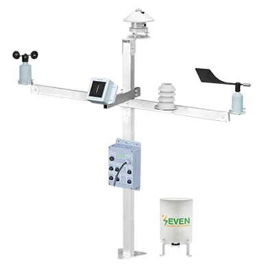
Compact Weather Stations are systems integrating multiple environmental measurements within a single compact enclosure.
The Compact Weather Station shall be capable of measuring at least the following parameters:
- Reference Cell (Irradiance Sensor), Plane of Array irradiance (Plane of Array – POA): It shall comply with Section 3. IRRADIANCE SENSOR
- Pyranometer, Global Horizontal Irradiance (Global Horizontal Irradiance – GHI): It shall comply with Section 4. PYRANOMETER
- PV Module Temperature Sensor: It shall comply with Section MODULE TEMPERATURE SENSOR
- Ambient Temperature Sensor: It shall comply with Section AMBIENT TEMPERATURE SENSOR
- Relative Humidity and Pressure Sensor: It shall comply with Section 9. RELATIVE HUMIDITY SENSOR
- Wind Speed Sensor: It shall comply with Section WIND SPEED SENSOR
- Wind Direction Sensor: It shall comply with Section WIND DIRECTION SENSOR
- Precipitation Sensor: It shall comply with Section RAIN GAUGE
Mounting Structure: It shall be made of SS304 or higher-grade stainless steel. Its height shall be at least 1 meter and it shall withstand a wind speed of at least 150 km/h. Calculation details demonstrating compliance with the specified wind load resistance shall be submitted to the Investor’s Representative during the approval stage.
The mechanical design of the station shall ensure that none of the integrated sensors are adversely affected by self-shading, thermal interaction, or airflow obstruction caused by other components of the station, regardless of installation orientation.
14.1. Standards and Compliance
All sensors used in the Compact Weather Station shall comply with the photovoltaic plant monitoring and meteorological measurement requirements defined within the scope of IEC 61724-1:2021 standard.
14.2. Communication
Communication shall be provided via a single RS-485 output using the Modbus RTU protocol and shall be compatible with standard PV data loggers and SCADA systems.
14.3. Installation and Mounting Conditions
The Compact Weather Station shall be supplied with all required mounting equipment and structural components suitable for long-term outdoor installation in photovoltaic power plants.
15. WARRANTY AND MAINTENANCE
15.1. Warranty Period
For all sensors, data loggers, communication equipment, and auxiliary components to be used in the PV plant, manufacturer warranty certificates shall be fully provided by the contractor. Warranty periods shall be applied as follows depending on the sensor type:
- Irradiance sensors (pyranometers and PV reference cells): Minimum 5 years
- External meteorological and auxiliary sensors (temperature, wind, humidity, precipitation, soiling, etc.): Minimum 2 years
The specified warranty periods shall cover measurement accuracy, electronic and mechanical integrity of the sensors, and monitoring continuity defined within the scope of IEC 61724-1.
Within the scope of warranty, measurement errors, electronic failures, hardware failures caused by environmental conditions (UV, humidity, temperature variations), and performance losses that may occur under normal operating conditions shall be included. The measurement accuracy of the sensors shall be guaranteed within the tolerances specified in the calibration certificate provided by the supplier.
In case of failures that may occur during the warranty period, the contractor shall repair the relevant equipment or replace it with an equivalent device with equivalent technical specifications within a maximum of 20 working days. During this period, in order to maintain monitoring continuity, a temporary sensor or an alternative measurement solution shall be provided.
All replacement and repair operations within the scope of warranty shall be carried out in accordance with the installation and commissioning requirements defined within the scope of IEC 61724-1, relevant electrical safety requirements, and manufacturer documentation; after replacement, the system shall be subject to recommissioning checks.
15.2. Spare Sensors
In order to ensure that measurement continuity is not interrupted in PV plant sites, spare units of critical sensors shall be kept readily available on site. The number of spare sensors shall be determined by considering the types of sensors used in the field, the performance monitoring class (IEC 61724-1 Class A/B/C), and the operational strategy. In particular, it is recommended to keep at least one spare unit for irradiance, temperature, wind, and soiling sensors.
In addition, according to the sensor density criteria defined in IEC 61724-1 based on site size, the number of sensors used in the field increases with installed capacity and area size. This situation is important not only for improving representativeness accuracy but also for preventing the monitoring system from becoming completely unavailable in case of any sensor failure. Therefore, in large and multi-orientation PV sites, the spare sensor capacity shall be increased in parallel with the increasing number of sensors. In this way, the monitoring of system performance can continue without interruption even in the event of failures that may occur in the field.
Spare sensors shall be of the same model or have an equivalent measurement class as the main sensors used in the field. This requirement is in line with the measurement continuity principles defined in IEC 61724-1 standard in order to maintain data consistency after sensor replacement.
Spare sensors shall be stored under the storage conditions recommended by the manufacturer until use. During sensor replacements, the date, time, and reason shall be recorded and maintained in the plant operation logs.
15.3. Maintenance and Cleaning Intervals
Maintenance and cleaning activities shall be carried out regularly and in a planned manner in order to ensure the measurement accuracy and continuity of the sensors used in PV plant sites. Since environmental contaminants that may accumulate on sensor surfaces can directly affect measurement results, these activities are an integral part of the performance monitoring process.
According to IEC 61724-1, maintenance and cleaning intervals shall be determined by considering the sensor type, monitoring class, and site conditions. In sites with Class A monitoring, this interval shall be 1 week. For soiling sensors, the soiled irradiance sensor shall also be cleaned in a way that is compatible with PV module cleaning schedules. The timing of panel cleaning shall be determined based on the values obtained from the soiling sensor. The soiling ratio obtained from the sensor shall be multiplied by the plant’s production revenue. If the resulting value exceeds the cleaning cost, the plant shall be cleaned. If there is no fixed soiling sensor installed in the plant, cleaning decisions may also be made using a portable soiling sensor. Operators managing multiple plants may use portable soiling sensors to manage cleaning intervals.
Especially in irradiance sensors, since soiling directly affects measurement accuracy, sensors with an automatic cleaning feature shall be used in regions with high soiling levels. Similarly, in regions where frost and snow events are frequent, irradiance sensors with a heating feature shall be used.
Within the scope of maintenance activities, the following checks shall be performed:
- Cleanliness of sensor surfaces shall be
- Sensor installation angles shall be
- Mechanical and visual inspection of mounting components and cabling shall be
- It shall be verified that the sensors are not exposed to shading and that there are no environmental
- Data logging and communication continuity shall be
For soiling sensors, the time difference between sensor cleaning and module cleaning shall be recorded.
All maintenance activities shall be planned by considering manufacturer recommendations and site conditions and shall be recorded in a traceable manner. Weekly inspections shall be recorded.
16. DOCUMENTATION
The supplier shall provide all technical documentation in an up-to-date and accessible manner to ensure that the installation, commissioning, operation, and maintenance processes of the system can be carried out properly and completely.
The documents to be provided shall include at least the following:
- User Manuals: They shall clearly define and describe the operating principles, normal operating conditions, basic functions, and safety warnings of the sensors and related equipment.
- Installation Instructions: They shall include implementation principles related to mechanical placement, orientation, environmental conditions, and mounting equipment, with sufficient clarity to enable correct installation by field teams.
- Calibration Certificates: They shall include factory calibration data of the sensors, calibration date, and measurement uncertainty and accuracy information.
- SCADA Integration Information: They shall include integration documentation covering communication protocols, data points, addressing structure, units, and alarm definitions.
All documents shall be provided in digital format, suitable for long-term archiving, and made readily available for use by field and control centre personnel.