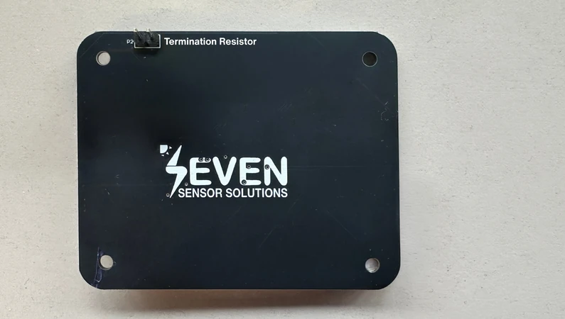
Modbus RTU Communication Issues
You wire your sensors, turn on the datalogger, and instead of irradiance or temperature readings you see “timeout”. You have, certainly, encountered such an issue when commissioning a weather station through the RS-485 bus.
The point is that most of the communication issues with Modbus protocol are fairly predictable. Each problem has a small set of possible causes which, knowing how to decode the error codes, can be identified in approximately one hour at the location. This article explains what timeout, CRC and “no response” errors mean and what usually causes them in meteorological sensor networks.
As a brief answer, the “Timeout” or “No response error” message signifies that the appropriate response message has not been received on time from the slave. The reason could be either an inappropriate slave address, baud rate and parity mismatch, or improper wiring of “Data +” and “Data -” lines. “CRC error” signifies that the reply received from the slave has been corrupted during transmission and the reasons could be noise, improper termination, incorrect grounding or inappropriate cables being used.
How does the Modbus RTU Protocol Transmit?
The protocol operates on a client-server basis (master-slave). The master node sends out a request, to which only one slave node responds. Slave nodes have their own slave address that lies within the range of 1 to 247.
Structure of messages contains slave address, function code, data and 16 bit CRC. Messages are divided by the period of silence for at least 3.5 characters time. It is necessary to remember this feature: if the slave receives a corrupted message, then it does not send an error message, it ignores this request. That is why, for the master a corrupted message is nothing and leads to a timeout.
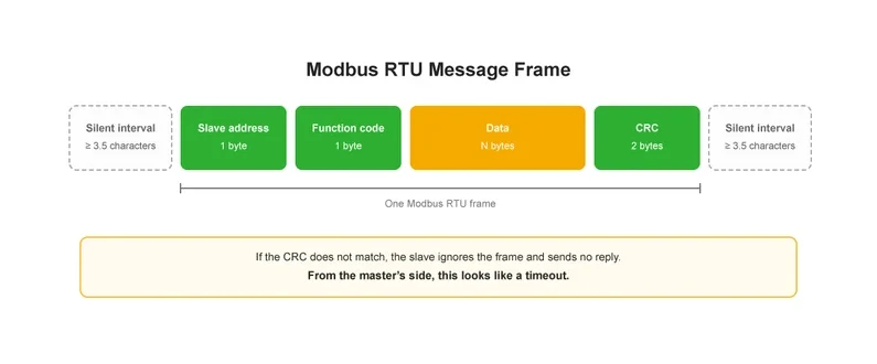
Modbus RTU Message Frame
What is the difference between a timeout, CRC error and an exception?
The following table briefs the difference between the modbus error types.
What Can Cause a Modbus Communication Error or Timeout?
Here are a few things that need troubleshooting in order of how frequently they occur:
- Incorrect slave ID number. Master is addressing device #1 but sensor has an ID of #3. Two devices having the same slave ID respond simultaneously, causing CRC errors.
- Incompatible serial settings. Baud rate, parity and stop bit parameters should be exactly the same for all devices and for the master controller. Serial settings 9600 8N1 and 9600 8E1 may look alike but never communicate.
- Swapped A and B pins. Manufacturers have different ways of labeling RS-485 terminals (A/B, D+/D−, +/−). One of the fastest tests when a newly connected device does not respond is swapping its two data wires.
- Power issues. Verify the supply voltage level at the sensor end as well, not just at the source of power. Voltage drop over long cables may cause the device to operate out of range.
- Too small timeout value or too frequent polling. If the master polls too many devices with very short timeouts, some slower devices may fail to reply. Extending the timeout value or inserting a delay between polls usually fixes the issue of “random” timeouts.
- A conductor break. Splice points and junction boxes are common problem locations. Read our guide on extending Modbus communication range and splicing wires.
- Two masters on the same line. Modbus RTU protocol supports only one master on a bus. If a datalogger and a SCADA gateway poll the same bus, their messages overlap.
What Triggers CRC Errors in RS-485 Line?
CRC error means poor signal quality. The data is coming through, but something happens with the bits while the information is being transmitted.
- Incorrect or missing termination. An RS-485 mainline should be terminated with a 120 Ω resistor only at its both ends. It is as detrimental to terminate all devices in an RS-485 network as not to terminate any.
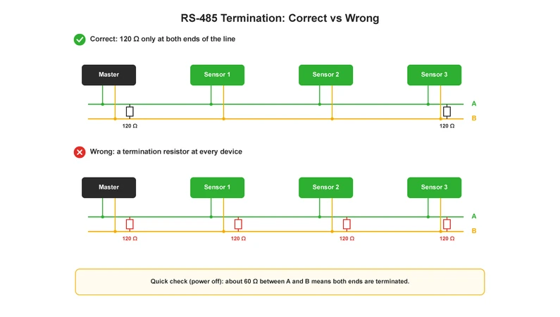
RS-485 Termination: Correct vs Wrong
SEVEN sensors provide you with the ability to activate the termination resistor via the user interface. This makes your job much easier on site.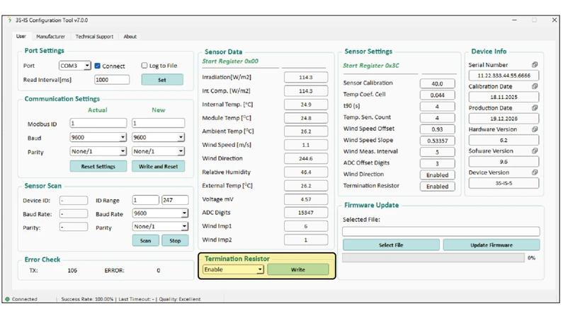
Activate the termination resistor online through SEVEN GUI
- Inadequate cable. For RS-485, you need a twisted pair cable with characteristic impedance around 120 Ω (preferably shielded). Read our article about RS-485/Modbus communication cable requirements.
- Parallel communication cables to power cables. The placement of Modbus cable along with AC and DC cables of inverters in one tray is one of the most frequent sources of noise in PV systems. Make sure to keep them separated from each other.
- Improper grounding. Potential difference in grounding between devices, or grounding of shield at multiple points, may result in noise. Study ground wire and how to install it between sensors.
- Star configuration and long stubs. The RS-485 network was intended to have a daisy chain configuration. Branching and long stubs will cause reflections. Check out our guide to a daisy chain configuration.
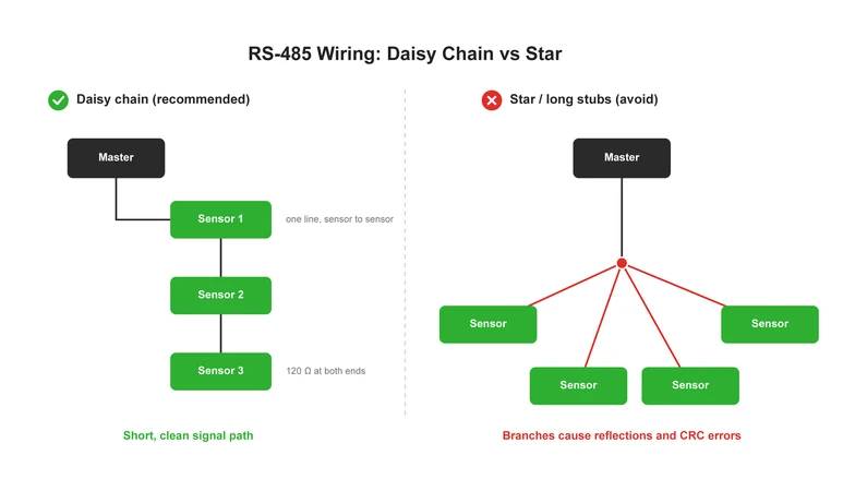
RS-485 Wiring: Daisy Chain vs Star
What do Modbus exception codes mean?
Receiving an exception code means that the link is correct, and the device responds to the request. The problem lies in your request.
Comment on register shift: in technical literature, 30001 (input registers) and 40001 (holding registers) both correspond to protocol address 0 in their own register type. Some software uses the first notation and some the second, so if your values are shifted by one register, this is the first thing to check. And if there are no errors at all but a 32-bit value is totally wrong, check the word order (register order) for 32-bit values in the master settings.
Having Problems with your Modbus Line?
In case you are setting up your weather station which has SEVEN sensors and the datalogger is not communicating with them, we have a solution for this problem using SEVEN Remote Setup Service. Please write to our technical team and let us know about your wiring and communication parameters.
Frequently Asked Questions Related to Modbus RTU Communication Errors
Is there a risk of damaging the device if I reverse A and B wires?
No, not in a usual installation. The data exchange between two devices is impossible until the connection wires are properly established.
How many sensors can I connect through one cable RS-485?
According to the standard, it is possible to connect 32 unit loads. In addition, reduced loads transceivers allow more connections, but in reality, the distance of the cable, baud rate, and polling period affect the number of sensors which can be connected to each cable.
Why do I receive incorrect values while there are no communication errors?
The most common reasons for receiving incorrect values are: a one register offset, incorrect order of words for 32-bit values, and missing scaling factor.
What is the maximum RS-485 bus length?
Approximately 1,200 m in total at low baud rates. As the baud rate increases, the possible length decreases.
References
7
View Sources
Close
-
Modbus Organization, MODBUS Application Protocol Specification V1.1b3. https://modbus.org/docs/Modbus_Application_Protocol_V1_1b3.pdf
-
Modbus Organization, MODBUS over Serial Line Specification and Implementation Guide V1.02. https://modbus.org/docs/Modbus_over_serial_line_V1_02.pdf
-
TIA/EIA-485-A, Electrical Characteristics of Generators and Receivers for Use in Balanced Digital Multipoint Systems.
-
SEVEN Sensor Solutions, RS-485 / Modbus Communication Cable Specifications. https://www.sevensensor.com/rs-485-modbus-communication-cable-specifications
-
SEVEN Sensor Solutions, What is Daisy Chain Connection? How to Make Daisy Chain Connection Between Sensors? https://www.sevensensor.com/what-is-daisy-chain-connection-how-to-make-daisy-chain-connection-between-sensors
-
SEVEN Sensor Solutions, What is a Ground Connection? How to Make a Ground Connection Between Sensors? https://www.sevensensor.com/what-is-a-ground-connection-how-to-make-a-ground-connection-between-sensors
-
SEVEN Sensor Solutions, How to Increase Modbus Communication Distance? https://www.sevensensor.com/how-to-increase-modbus-communication-distance-things-to-consider-when-splicing-cables-on-modbus-lines